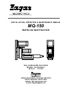
background image

INSTALLATION, OPERATION & MAINTENANCE MANUAL


MQ-150


Ball Screw Quill Feed Unit 


Basic Unit Model MQ-150 (749-900) 

MANUAL: 790-7493-0203-1 

Revised: 

12/11/02 


24000 Lakeland Blvd., Cleveland, OH 44132 

216/731-0500 FAX: 216/731-8591 

website: http://www.zagar.com 

E-mail: zagarfeed@aol.com 


Summary of Contents for MQ-150

Page 1: ...MANUAL MQ 150 Ball Screw Quill Feed Unit Basic Unit Model MQ 150 749 900 MANUAL 790 7493 0203 1 Revised 12 11 02 24000 Lakeland Blvd Cleveland OH 44132 216 731 0500 FAX 216 731 8591 website http www...

Page 2: ...oubleshooting 22 Options and Accessories na Appendix 23 Parts List Refer to assembly drawing 749 901 Dimension Information Appendix Drawing 749 901 The information in this document is subject to chang...

Page 3: ...h are inherently maintenance items The spindle axis may consist of a standard fixed speed AC induction motor an inverter drive for variable speed or an AC brushless servo motor for tapping and two axi...

Page 4: ...cing All moving parts must be stopped before servicing or tooling changes Use extreme caution when operating or servicing this equipment Think Safety First Use caution with all pneumatic and or hydrau...

Page 5: ...e 1 1 2 91 1 Depth Control Programmed to 10 microns Quill Diameter 55mm Spindle Noses ASA sizes 625 750 875 1 062 1 25 1 375 Metric ASA sizes 25 32 45 50mm Jacobs taper 1 3 33 sizes 16 and 25 single a...

Page 6: ...g device which is specified at the time of order and is connected to the front barrel of the unit Each of the mounting devices share the same features of four holes for bolting the unit to a mounting...

Page 7: ...provided with all servo controls No additional programming or programming experience is required to use these controls The operator interface provides an easy to use prompt type system for data entry...

Page 8: ...ace to properly adjust for speed and feed when a pulley ratio is changed This ratio is entered at the factory for the set of pulleys that are shipped with the unit The speed or speed range of the unit...

Page 9: ...ia dry relay contact see electrical prints OUTPUT 0 is for cycle complete and OUTPUT 4 is for faults Check the Hardware Reference guide in the Appendix for detailed on the input and output specificati...

Page 10: ...not detecting repeatably too far away it will require minor adjusting The sensor should be approximately 1mm away from the quill It has a maximum sensing distance of 2mm To adjust this first make sure...

Page 11: ...ing this file The unit performance can be drastically affected if these parameters are altered Damage to the unit can result Zagar does not bear any responsibility for any problems or damage resulting...

Page 12: ...2 cable connected to and set the baud rate at 9600 Hit OK To check for proper communication select TOOLS and TERMINAL You should get a blank window Hit return and you should see a right pointing arrow...

Page 13: ...d only requires a short period of time to learn A quick reference sheet is provided in the Appendix section Use this sheet to see the sub menu structure of the Zagar program The operator interface is...

Page 14: ...settings to be changed Enter driver pulley of teeth operator entry Enter driven pulley of teeth operator entry EXIT F6 Exits to SETUP MENU 1 without changing settings Select F5 Goes to TOOL SELECT fo...

Page 15: ...stage You will be prompted for which drill stage you are entering data for Enter feed rate Enter feed rate for each drill stage in Inches Per Revolution Enter rpm Enter rpm for each drill stage Enter...

Page 16: ...ids are destructive to the lubrication particularly the quill lubrication so it may be necessary to inspect and re lubricate this component more frequently The benefit gained by the use of this type o...

Page 17: ...before adding grease Pump grease until it is visibly ejected from hole on opposing side Replace set screw into relief hole on opposite side Grease fills an undercut pocket inside of cylindrical housi...

Page 18: ...ntal increases usually about every 10 15 minutes until no temperature rises are experienced The ideal equilibrium operating temperature is 35 deg C to 40 deg C 95 deg F to 105 deg F NOTE Maximum beari...

Page 19: ...66 inside of the internal nut and remove the internal nut Unthread the lock nut 10 727 4 and the spindle bearings 10 0201 2043 3 can now be pulled off with proper pulling equipment Removing spline dri...

Page 20: ...truction below Disassembling quill and ball screw assembly 1 To remove quill 749 910 remove set screws 12 525 16 and using strap wrench unthread quill from ball screw See note below 2 Remove lock nut...

Page 21: ...er torque specs as shown on drawing 749 901 8 For bushing style pulleys loosen and remove 3 hex head screws in bushing Replace same screws into jackscrew holes in bushing and by tightening each one a...

Page 22: ...uit has been broken Verify e stop buttons input 7 on motion controller c memory corrupt use new Battery backup in motion controller has failed Send motion controller back to Baldor for inspection if u...

Page 23: ...23 Operation and Maintenance Manual MQ 150 Ballscrew Feed Unit Appendix...

Page 24: ...24 Operation and Maintenance Manual MQ 150 Ballscrew Feed Unit Dimensional Information MQ 150 MQ 150 BALLSCREW FEED UNIT...

Page 25: ...25 Operation and Maintenance Manual MQ 150 Ballscrew Feed Unit...

Page 26: ...ing Center Heads Rotating Heads Workholding Fixtures Specializing in Collets and Collet Fixtures Standard and Special Manual Air and or Hydraulic Automated Index Internal or External Clamping Fixtures...

Reviews: