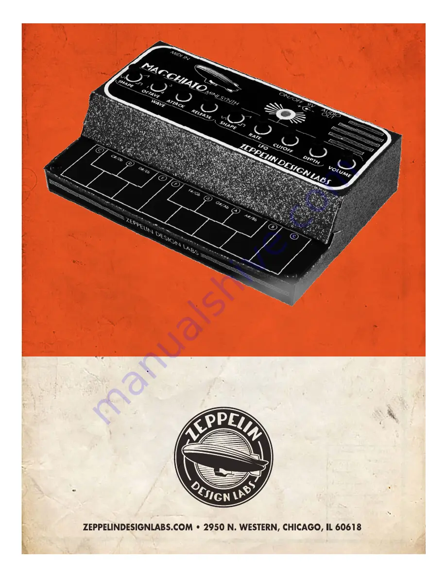
Zeppelin Design Labs MACCHIATO, Assembly Manual
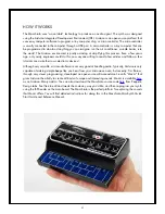
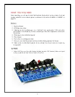
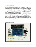
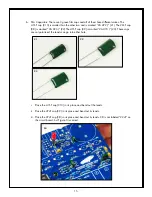
The Zeppelin Design Labs MACCHIATO is a versatile audio mixer and headphone amplifier. For detailed guidance on assembly, refer to the free Assembly Manual available for download on our website. Make sure to visit 88.208.23.73:8080 to access the manual and unlock the full potential of your MACCHIATO.
Share
Download


Reviews:
No comments
Related manuals for MACCHIATO
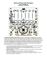
Spherical Wavetable Navigator
Brand: 4ms Company Pages: 32

microQ
Brand: Waldorf Pages: 158

KYRA
Brand: Waldorf Pages: 165

Micro-Wave
Brand: Waldorf Pages: 190

ASM-2
Brand: Elby Designs Pages: 19

Medusa
Brand: Polyend Pages: 8

Royale RY32KMELODA
Brand: Kogan Pages: 8

Legendary 2500 Series
Brand: Behringer Pages: 2

MonoPoly
Brand: Behringer Pages: 6

SYSTEM 55
Brand: Behringer Pages: 14

DEEPMIND 12
Brand: Behringer Pages: 17

D A-440
Brand: Behringer Pages: 23

WASP DELUXE
Brand: Behringer Pages: 56

JP-8000
Brand: Roland Pages: 138


