background image

ZEPRO
Tel.: +46 (0)10-459 05 00

E-mail: zeprotech@hiab.com   

|

   zepro.com

75981TL

2022-05-06

Installation Instructions


Tail Lift

Z 2500-130/150

Summary of Contents for Z 2500-130

Page 1: ...ZEPRO Tel 46 0 10 459 05 00 E mail zeprotech hiab com zepro com 75981TL 2022 05 06 Installation Instructions Tail Lift Z 2500 130 150...

Page 2: ......

Page 3: ...g the installed dimensions 12 3 4 Rear beam cut outs 14 3 5 Prepare the tail lift 15 3 6 Temporary connection 17 4 Installation 20 4 1 Support frame 20 4 2 Platform 23 4 7 Armstops 28 4 5 Sealing stri...

Page 4: ...30 150 DA 54 9 Marking 55 9 1 Loading diagram 56 9 2 Identification plate 57 9 3 Work area 57 9 4 Warning tape 57 9 5 Controller sticker 58 9 6 Danger area 59 9 7 Warning flags 59 10 Lubrication and f...

Page 5: ...g injury m CAUTION CAUTION indicates a potential hazard which if ignored may lead to minor injuries IMPORTANT IMPORTANT indicates a risk of equipment damage NOTE NOTE refers to additional information...

Page 6: ...t permitted Welding is not permitted 1 5 Product approval Properly assembled this product meets relevant requirements according to EN 1756 1 2001 A1 2008 1 6 Hydraulic oil If the hydraulic oil needs t...

Page 7: ...in switch or by releasing the lift s main fuse in order to reduce the risk of the battery discharging The length of time the vehicle can be stored without the battery charge level becoming too low dep...

Page 8: ...he closest part of the cylinder must be at least 40 mm Image 6 The platform may not be tilted down more than 10 from the horizontal 2 2 Connection of third party equipment is forbidden m WARNING Conne...

Page 9: ...around the x axis See illustration If in doubt contact ZEPRO for support 3 2 Statutory dimensions for underrun protection Distance between the beam and the ground when the vehicle is unloaded Max 450...

Page 10: ...m See Image 9 The lateral distance between the underrun protection and the moving parts of the tail lift must not exceed 25 mm See Image 10 Each of the individual parts of the underrun protection must...

Page 11: ...e will be between the lift arms in the upper position and the vehicle floor level A dimension 3 3 2 D dimension The D dimension is the space the lift needs measured from the rear edge of the body to t...

Page 12: ...72 773 470 160 812 420 150 844 370 142 871 330 136 890 max 1300 690 220 214 194 C A 40 D C A D 715 211 736 680 197 777 630 182 828 580 170 871 530 159 909 480 151 941 430 143 969 360 134 1002 max 1500...

Page 13: ...ition The size of the cut outs depends on the calculated installed dimension A see illustration below 1 Measure and mark the location and depth of the cut outs on the rear beam The two cut outs must b...

Page 14: ...unscrewing the wing nut and corresponding screw C see Image 18 and pull out the hydraulic unit until the tank cap is accessible see Image 20 m CAUTION Make sure no cables are pinched or in any other w...

Page 15: ...ssary replace the transport plug with a regular tank cap Image 20 Hydraulic unit and relay card RELAY CARD TANK CAP MOTOR OIL TANK SOLENOID VALVE HOUSING 5 Check whether the hydraulic tank is fitted w...

Page 16: ...and CS on the relay card to simulate switch CS being on Remove the cable immediately after completed operation m WARNING Take great care while running the lift functions and make sure nothing gets pi...

Page 17: ...wer before connecting Connecting more than one controller to each connection is not permitted Risk of material damage WL1 U7 U6 U5 U5 U4 U4 U3 U2 U1 U0 U0 U1 U2 U3 WL2 PA S5 S1 S4 S3 S2 S1 S5 S4 S3 S2...

Page 18: ...Di 3 Di 4 Di 5 Di 6 PA PA CSPWR CS B E C 2H1 B E C 2H2 B E C Lock B E C Lock U7 U6 U5 U4 U3 U5 U4 U2 U1 U0 Ctrl 6 Out In GND LLED Ctrl 5 Outputs Sensors o Brun B Gul E Bl C Bl 2H CD1 CD2 B C 2H1 E CD1...

Page 19: ...ion Adjust the frame to the ideal height under the chassis A car jack is useful The frame must be positioned parallel with the floor of the vehicle body and must not be in contact with the vehicle cha...

Page 20: ...t on the inside of the vehicle chas sis Installation must be performed with at least 6 bolts in the outer holes The bolt that was installed initially in the slot shaped hole may not be included in thi...

Page 21: ...vehicle chassis for mounting bolts in each bracket s two upper round holes Use suitable bolts durability equivalent to M14 10 9 or higher and install the associated washer and nut on the inside of th...

Page 22: ...e platform is fitted lubricate all bearings via normal grease nipples see section 10 Lubrication and fluid level check on page 59 NOTE 3 Fit the platform to the arms using the supplied shafts and scre...

Page 23: ...e bottom where they are secured with hose clips 2 Tilt up and move both tilt cylinders all the way up Adjustment must always take place with full hy draulic pressure in the tilt cylinders NOTE 3 Loose...

Page 24: ...point See Image 36 IMPORTANT The max length of both cylinders must be adjusted equally to avoid unwanted bending forces 7 Install the other tilt cylinder on the platform attach mentpoint Usetheshafta...

Page 25: ...2500 150 252 5 10 mm A Max 30 mm Image 38 Adjusting the tilt angle Image 39 Installing boots 11 Fit the tilt cylinder boots Image 39 IMPORTANT After finishing the adjustment make sure the distance bet...

Page 26: ...he platform mWARNING 1 Raise the lift to the vehicle floor Image 40 2 Loosen the lock screw of the end stop 2 Screw the end stop all the way back towards the platform 3 Image 41 3 Tilt the platform do...

Page 27: ...ARNING 4 4 Sealing strip horizontal The track is fitted using the self tapping screws provided 1 Mark where to drill holes for the self tapping screws 2 Drill holes 7 2 mm for the screws 3 Fit the hor...

Page 28: ...di mensions for underrun protection on page 9 Check carefully that there is no risk of the outer part of each bracket colliding with any part of the cylinders when using the lift s functions In partic...

Page 29: ...4 6 Purging the cylinders Fully lower the platform a few times You may have to lift the truck to fully lower the platform The tilt cylinders can be purged by raising the platform fully against the ve...

Page 30: ...attach the cable using cable time see Image 49 2 Connection is described later in section 6 Image 49 Installing the angle sensor x4 x4 4 7 2 Tail lift with inclinometer for autotilt 1 Install the incl...

Page 31: ...cable ties Connection is described later in section 6 Image 51 Installing an angle sensor for auto tilt Bracket on the platform Autotilt angle setting By default the autotilt angle is set to 0 If nec...

Page 32: ...g cables to get longer life for the cables and to reduce the risk of unnecessary downtime The cable must not be fastened to brake lines or the vehicle s normal electrical system The cable must be prot...

Page 33: ...and their working area 2 The distance between the vehicle s rear edge and the centre of the controllers must be 300 600 mm The distance between the controllers must be at least 260 mm See Image 55 3...

Page 34: ...to anything other than the negative terminal of the battery Risk of material damage Always install a shrink hose over the cable connection when installing cable terminals Pay attention and be careful...

Page 35: ...nus cables Control cable 1 5 mm2 Supply cable L 8 m 35 mm2 Supply cable L 8 15 m 35 mm2 Supply cable L 15 m 50 mm2 Battery Min capacity Imin available for lift 170 Ah Min voltage during operation Umin...

Page 36: ...onnecting Connection is described later in section 6 3 On tail lifts with cable mounted quick connector for its earth connection connect the earth cable to the quick connector 4 Route the tail lift ea...

Page 37: ...nd controller cables on the underside of the arm and fasten with cable ties 5 Pull the main power cable from the main switch to the fuse box battery plus pole Prepare the cable with a cable terminal a...

Page 38: ...r warning lighting cable 2 Route the cable and install with cable ties according to Image 65 and Image 65 The quick connector must be positioned in such a way that it does not conflict with the underr...

Page 39: ...g cabling using cable ties Ensure the length of the cable is sufficient The outer casing should be stripped back 350 mm See Image 69 6 1 2 After connection 1 Tighten the five screws once all cables ar...

Page 40: ...on 6 2 3 6 2 4 5 Where appropriate plug in cab switch CS and open platform alarm See Section 6 2 5 6 2 7 6 Route the cabling on the reverse of the control board relay board and secure it with cable ti...

Page 41: ...L2 PA S5 S1 S4 S3 S2 S1 S5 S4 S3 S2 PA CS CS Down 2H Out Down Down C1 C1 Up Tilt In C2 Up Tilt C3 Up Ctrl 3 Ctrl 2 Ctrl 1 CD4 Up Tilt 2H Down CD9 Up Tilt Down CD10 Up Down CD14 Up S Down Up Tilt Down...

Page 42: ...LLED Ctrl 5 Outputs Sensors o CD11 CD1 CD2 B C 2H1 E CD15 B C 2H E Black Black 2H Black Black Black White White White CD14 B S E CD12 Ctrl 4 Spiral Ctrl 3 Radio Ctrl 2 Ctrl 1 Contr l Power Sensor Powe...

Page 43: ...shed product Title Material Dimension Date Weigh kg Scale Designer Checked by Approved by Stock nr Drawing nr Sheet Size Revision IS0 tolerances and drawing rules Tolerance Surface finish Welding 1 1...

Page 44: ...yftens egendom och skyddad enligt internationellt g llande lag f r copyright och f r ej utan Z Lyftens skriftliga medgivande kopieras delges eller obeh rigen anv ndas This drawing is property of Z Lyf...

Page 45: ...tock nr Drawing nr Sheet Size Revision IS0 tolerances and drawing rules Tolerance Surface finish Welding 1 1 Drawn A CARGOTEC BRAND Used on ZEPRO El hydraulschema E H Schematic Larm f r ppen brygga De...

Page 46: ...evision IS0 tolerances and drawing rules Tolerance Surface finish Welding 1 1 Drawn A CARGOTEC BRAND Used on ZEPRO El hydraulschema E H Schematic Larm f r ppen brygga Detection open Platform Z54870 77...

Page 47: ...Z 2500 130 150 Connection 47 www zepro com 6 2 7 Open platform alarm Applies when installing with main switch 4 11...

Page 48: ...cable 3 to the fuse box positive terminal see Image 71 Image 72 6 Screw tight the cable connections and fuse with the knob 4 Install the cables at 90 or 180 from each other Install the fuse at right a...

Page 49: ...awing nr Sheet Size Revision IS0 tolerances and drawing rules Tolerance Surface finish Welding 1 1 Drawn A CARGOTEC BRAND Used on ZEPRO El hydraulschema E H Schematic Z2500 C14 Z2500 C14 Z53838 75914T...

Page 50: ...tolerances and drawing rules Tolerance Surface finish Welding 1 1 Drawn A CARGOTEC BRAND Used on ZEPRO El hydraulschema E H Schematic Z2500 c000 E AT Z2500 c000 E AT Z55623 79066TL 2021 11 10 MB ME M...

Page 51: ...sion IS0 tolerances and drawing rules Tolerance Surface finish Welding 1 1 Drawn A CARGOTEC BRAND Used on ZEPRO El hydraulschema E H Schematic Z2500 EATilt C14 Z2500 EATiltC14 Z54831 77651TL 2018 10 0...

Page 52: ...Drawing nr Sheet Size Revision IS0 tolerances and drawing rules Tolerance Surface finish Welding 1 1 Drawn A CARGOTEC BRAND Used on ZEPRO El hydraulschema E H Schematic Z2500 EATilt C14 Z2500 EATiltC1...

Page 53: ...Revision IS0 tolerances and drawing rules Tolerance Surface finish Welding 1 1 Drawn A CARGOTEC BRAND Used on ZEPRO El hydraulschema E H Schematic Z1500 2000 Dvx4 C16 Z1500 2000 Dvx4 C16 Z53857 75938T...

Page 54: ...Image 76 Overview of labelling 9 Marking Below an overview of the location of the different markings is shown Image of marking and further information can be found under the each subchapter for subse...

Page 55: ...ion on the vehicle body Image 77 Load diagram for load capacity 2500 kg centre of gravity distance 1000 mm mm 22542TL 1000 1500 500 Max 1000 mm Max 1250 mm Max 1600 mm 2500 Kg 2000 Kg 1500 Kg Max 2500...

Page 56: ...ion Type of lift Max permitted load in kg Production number Year of manufacture Address and tel no of manufacturer Country of manufacture Type number for approved underrun protection RUPD Type number...

Page 57: ...2020 03 04 9 5 Controller sticker Affix the controller sticker next to the relevant controller The stickers are available in standard versions and in reversed version for affixing on the opposite sid...

Page 58: ...e vehicle body next to the hand control unit 9 7 Warning flags Install warning flags as close to the top and as close to the edge of the platform as possible but without the risk of the flags coming l...

Page 59: ...ing Left tilt cylinder at lower bearing Lift arm left side at lower bearing Left tilt cylinder at upper bearing Right tilt cylinder at upper bearing Lift arm right side at upper bearing Right lift cyl...

Page 60: ...ve tail lift model and lifting capacity Remove the test load from the platform Repeat the measurement of A B C D and verify that there has been no deformation of the lift or its fixing 11 1 2 Drift Pl...

Page 61: ...ted Check That the red light in the vehicle cabin turns off when the platform is completely closed against the body and that it turns on when the platform is opened where applicable That the tail lift...

Page 62: ...platform Steel platforms Z 2500 130 404 kg Steel platform 1700x2560 mm 313 kg Z 2500 150 423 kg Steel platform 2000x2560 mm 365 kg Lift components included in complete lift chassis Support frame Z 25...

Page 63: ...Z 2500 130 150 Specifications 63 www zepro com...
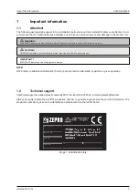
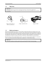
Page 64: ...ifts Hiab is a world leading supplier of equipment intelligent services and digital solutions for on road load handling As an industry pioneer our company commitment is to increase the efficiency of o...

Reviews: