Zeta Alarm Systems INFINITY ID2, Installation Manual
The Zeta Alarm Systems INFINITY ID2 is a cutting-edge security system designed to protect your home or business. Ensure a smooth installation process by downloading the free Installation Manual from 88.208.23.73:8080 to easily set up and configure your alarm system. Get peace of mind with this state-of-the-art security solution.
Share
Download

Reviews:
No comments
Related manuals for INFINITY ID2

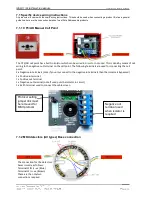
EBL512 G3 5000
Brand: Panasonic Pages: 134

LW401
Brand: Faraday Pages: 35

BSR-1000
Brand: olympia electronics Pages: 71

WES3
Brand: Ramtech Pages: 64

Premier M plus
Brand: Zeta Pages: 16

Premier M plus
Brand: Zeta Pages: 22

zp1-f Series
Brand: Ziton Pages: 2

ZP2 Series
Brand: Ziton Pages: 2

NPAD 2
Brand: Zeta Pages: 33

SP-64
Brand: Zeta Pages: 23

JUNIOR V3
Brand: Global Fire Equipment Pages: 21

UniNet 2000 AFP-300 NION
Brand: Notifier Pages: 32

SS24ADAS Series
Brand: System Sensor Pages: 4

FD 7120
Brand: UniPOS Pages: 2

LCD-80FC
Brand: Fire-Lite Pages: 32

MS-700ID SERIES
Brand: Mircom Pages: 2

80-210
Brand: Zeta Alarm Systems Pages: 3
EN54
Brand: Zircon Pages: 41


