background image


Schlossgasse 10   CH-4125 Riehen   Tel.: +41 61 645 98 00   E-Mail: info@zimmerliag.com   www.zimmerliag.com 


Seite 1 / 12


Operating manual 

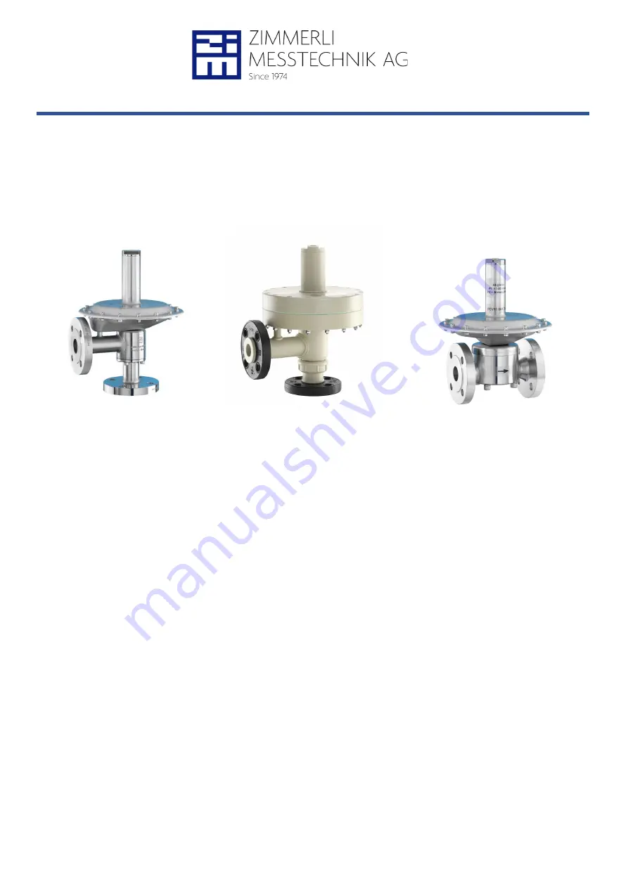
For low pressure relief valve 

Type LPS… ZM-B… and ZM-B/R… 


LPS25 


LPSK25 


ZM-B15 

ZM-B25 

ZM-B/R 


Contents 

1


General information .................................................................................................................................................... 2


2


Warranty provisions .................................................................................................................................................... 2


3


Purpose ...................................................................................................................................................................... 2


3.1


Intended use .......................................................................................................................................................... 2


3.2


Assembly work on the pressure regulator: ............................................................................................................ 2


4


Safety provisions ........................................................................................................................................................ 3


5


Material resistance ..................................................................................................................................................... 3


6


Startup ........................................................................................................................................................................ 3


6.1


Before installation .................................................................................................................................................. 3


6.2


Installation .............................................................................................................................................................. 3


6.3


Assembly position and installation ......................................................................................................................... 3


6.4


Configuring the setpoint ......................................................................................................................................... 5


7


Impulse line (C-connection) ........................................................................................................................................ 5


8


Maintenance and repairs ............................................................................................................................................ 5


8.1


Inspection intervals ................................................................................................................................................ 5


9


Model selection ........................................................................................................................................................... 6


10


Code: ZM-B15, relief valve ......................................................................................................................................... 7


11


Code: ZM-B25, relief valve ......................................................................................................................................... 8


12


Code: ZM-B/R15, non return valve ............................................................................................................................. 9


13


Code: ZM-B/R25, non return valve ........................................................................................................................... 10


14


Code: LPSK25, relief valve....................................................................................................................................... 11


15


Code: LPS25, relief valve ......................................................................................................................................... 12


Summary of Contents for LPS Series

Page 1: ...bly work on the pressure regulator 2 4 Safety provisions 3 5 Material resistance 3 6 Startup 3 6 1 Before installation 3 6 2 Installation 3 6 3 Assembly position and installation 3 6 4 Configuring the...

Page 2: ...cing parts and or for procuring spare parts 3 Purpose These type of pressure regulators are suitable for various tasks e g inerting containers with inactive gases The degree of protection for the stan...

Page 3: ...materials has to be checked see the corresponding chapter of this operating manual Newly installed pipelines must be fully rinsed clean to eliminate mechanical residues It must be ensured that the pr...

Page 4: ...Furthermore it is recommended that you install one shut off valve each before and after the pressure regulator to simplify any maintenance work Furthermore a suitable filter must be installed before t...

Page 5: ...ise rotation Decreasing primary pressure p1 Counterclockwise rotation Increasing primary pressure p1 7 Impulse line C connection An impulse line must be able to communicate with the p1 side of the val...

Page 6: ...pheric pressure p1 mbar g primary p2 mbar g secondary La pression secondaire ou contre pression p2 est normalement atmosph rique p1 mbar g primaire p2 mbar g secondaire Werkstoff Material of construct...

Page 7: ...x 2025 mbar 13 50 mbar 8 50 mbar ZM B ZM B D Ds max 2055 mbar 15 100 mbar 10 100 mbar ZM B ZM B D Ds max 2100 mbar 20 200 mbar 15 200 mbar ZM B ZM B D Ds max 2200 mbar 25 500 mbar 2 20 500 mbar 2 ZM B...

Page 8: ...40 180 C 200 mm Viton 20 130 C 200 mm 10 20 50 100 200 500 Federbereich p1 prim r Spring range p1 primary Plage de r glage p1 primaire Horizontal 2 Vertical 3 Typ Type Type Dom Dome D me 8 13 mbar 3...

Page 9: ...al on request Sp cial nous consulter P V Membrane Diaphragm Membrane PTFE 40 180 C 200 mm Viton 20 130 C 200 mm 10 20 50 100 200 500 Federbereich p1 prim r Spring range p1 primary Plage de r glage p1...

Page 10: ...ad Filet DIN EN Gewinde Thread Filet DIN EN Gewinde Thread Filet DIN EN Gewinde Thread Filet ANSI Gewinde Thread Filet ANSI Gewinde Thread Filet ANSI TriClamp 50 5 mmDIN32676 B DIN EN Sonder auf Anfra...

Page 11: ...5 20 mbar 5 20 mbar LPSK LPSK D Ds max 1000 mbar 8 50 mbar 8 50 mbar LPSK LPSK D Ds max 1000 mbar 10 100 mbar 10 100 mbar LPSK LPSK D Ds max 1000 mbar 15 200 mbar 15 200 mbar LPSK LPSK D Ds max 1000...

Page 12: ...embrane Diaphragm Membrane PTFE 40 180 C 200 mm Viton 20 130 C 200 mm 10 20 50 100 200 500 Federbereich p1 prim r Spring range p1 primary Plage de r glage p1 primaire Horizontal 2 Vertical 3 Typ Type...

Reviews: