
1 & 2 Zone Fire Alarm Panels
System installation, operating &
maintenance instructions
These instructions cover the:
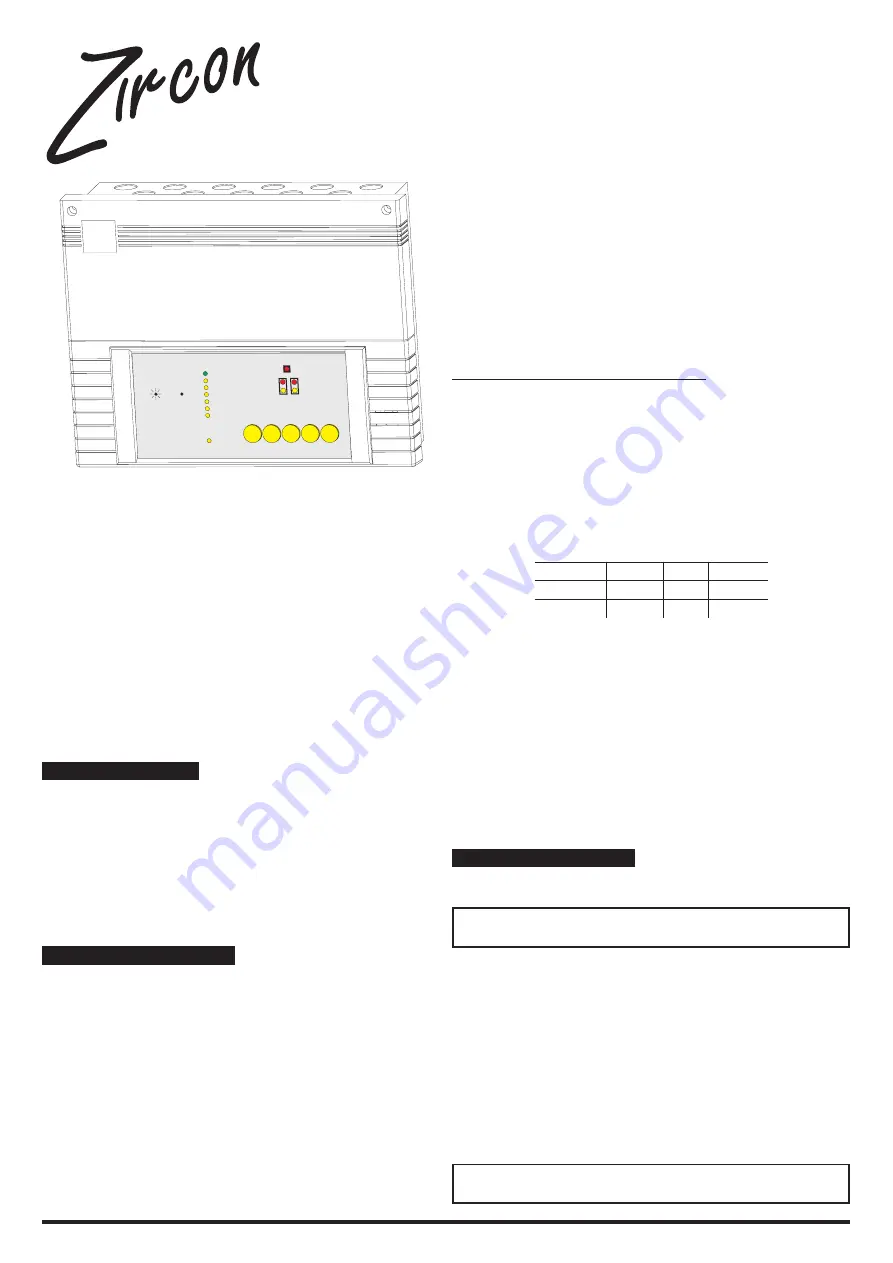
ZIRCONLC1 :
One-Zone Conventional Fire Panel
ZIRCONLC2 :
Two-Zone Conventional Fire Panel
The panels are designed to meet the requirements of EN54-2:1996 &
EN54-4:1996
Technical helpline:
☎
+44 (0) 1268 56 3256
This publication is issued to provide outline information only and is not deemed to
form part of any offer or contract. Our policy is one of continual improvement and
we reserve the right to vary details without prior notice.
General Description
Options included that are covered by EN54
ÿ
Test Condition (10.0)
ÿ
Fire Alarm Devices (7.8)
Ancillary functions provided but not required by EN54
ÿ
Class change
ÿ
Repeater
Technical Specifications
Power Supply requirements
10 - 15% 50Hz
Maximum Power consumption 50VA
Fuse rating - T125mA
The mains supply should be carefully wired using flat twin and earth of not
less than 1mm
2
between the mains connector block and an externally
mounted secure switched fused spur outlet with contact separation of at
least 3mm. The switched spur unit should be fused with a 2A fuse.
Battery
24 Hour standby 1 x 12 V 2.6 Ah (minimum)
or 3.3Ah (maximum)
Fuse rating - F1.6A
Weight
4.2 Kg (including 2.6 Ah battery & carton) approx.
Detection Circuits
20 smoke or heat detectors maximum per zone. (A maximum quiescent
current of 1.2mA is allowed per zone circuit)
30 Call Points maximum per zone.
Alarm Sounder Circuits
300mA total through 2 circuits.
Nominal Voltage 25.3V (+2.7V / -1V)
Fuse rating - F315mA
Auxiliary 24V Supply
This is specifically not for fire protection devices.
50mA maximum.
Nominal Voltage 25.3V (+2.7V / -1V)
Fuse rating - F125mA
Auxiliary Relay
Volt free change over contacts rated at 1A 30VDC Fuse Rating 1A
Note, the Auxiliary relay is configured as a fault relay, as standard (EN54
requirement), however the relay can be configured as an auxiliary fire
relay, by moving a jumper link from the fault position to the fire position on
the back of the PCB.
AUXILIARY RELAY
1
2
3
FAULT
NC
C
NO
FIRE
NO
C
NC
The N/C and N/O contacts change position, when the jumper is moved to
the fire position.
Class Change
Activated by using volt free N/O contacts between the -ve of AUX 24V
output and the CLASS CHANGE output.
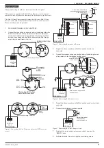
Cabling
Unless otherwise recommended, and taking into account voltage drop, not
less than 1mm
2
is recommended. Sounder circuits should use cable that
is fire proof. All cabling should be earthed to the metal back box via the
cable gland. Conductors carrying fire alarm power signals should be
separated from conductors used for carrying other systems.
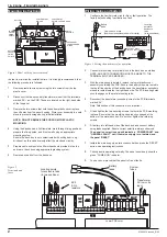
Installation information
Installation of this product must be carried out using the information
given in this leaflet by a qualified electrician.
Warning:
Before installation ensure the electrical supply is
isolated.
Installation of this product must be carried out in accordance with the
requirements of BS5839 Pt1 and EN54.
Mounting location considerations
The fire alarm control panel should be mounted near to a permanent, low
fire risk, Entry / Exit, for easy access by the Emergency Services. The
panel should not be mounted in direct sunlight, or in a place where the
ambient temperature is above 30 ºC (86 ºF).
Mains must not be capable of being accidentally disconnected and the
isolating switch should clearly state:
FIRE ALARM - DO NOT SWITCH OFF
Caution:
Anti static precautions should be taken when
installing the panel.
61640610 issue 6_8/02
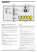
1
1
2
ZONE
FIRE
POWER ON
GENERAL FAULT
SYSTEM FAULT
TEST
DISABLE
POWER FAULT
SOUNDER
FAULT/DISABLE
LED Continuous
DISABLED
LED flashing
FAULT
SUPERVISOR
MODE
5
Select /
Lamp Test
4
Advance
3
Reset
2
Mute
Panel
1
Sounders
ON/OFF
FIRE
FAULT / DISABLED
To reset from alarm enter code
and press
SOUNDERS ON/OFF
followed by
RESET


