© 2014 UTC Fire & Security. All rights reserved.
1 / 4
P/N 501-1631ZE-1-06 • REV 06 • ISS 11MAR14
ZR432-2P Radio Multisensor (Optical/Heat)
Detector Installation Sheet
Description
The ZR432-2P Radio Multisensor (Optical/Heat) Detector is
specifically designed for use with the Ziton ZP2 (all versions)
and ZP3 (firmware versions 3.12 and later) addressable control
panels. When used with legacy Ziton ZP3 (firmware version
3.11 and earlier) or ZP5 systems, the detector functions and
installation methods may be different. These differences are
described in this installation sheet.
The detector is designed for use with wireless mounting bases
and radio loop modules. Refer to Table 1 for a complete list of
model numbers.
The detector incorporates a red LED for visual indication of the
alarm state. The ZR432-2P is designed for indoor use.
Table 1: Models
Number
Name
Detector
ZR432-2P
Radio Multisensor (Optical/Heat) Detector and
base, Polar White
ZX432-2P [1]
Multisensor (Optical/Heat) Detector, Polar White
Bases:
868 MHz systems
ZR401-3P
Ziton Protocol 868 MHz, Radio Sensor Base for
ZX432-2P with battery pack, Polar white
ZPR868
Ziton Protocol 868 MHz - Radio Loop Module
(RLM)
Legacy systems
ZP470
Ziton Protocol - Radio Loop Module (RLM)
ZR401-1
Ziton Protocol, Multisensor Radio Base
[1] Refer to ZX432-2P when purchasing the detector separately from
the ZR401-3P base.
Operation
868 MHz systems
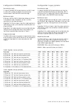
Subject to configuration, the detector can operate as a
multisensor, a smoke detector, or a heat detector. For detector
configuration details, refer to Configuration: 868 MHz systems.
Legacy systems
Subject to configuration and the detector base used, the
detector can operate as a multisensor, a smoke detector, or a
heat detector, as shown below.
Operation
Mounting base
Smoke detector
ZR401-1, ZR401-MS-2
Heat detector
ZR401-1, ZR401-MS-2
For detector configuration details, refer to Configuration:
Legacy systems.
Configuration: General
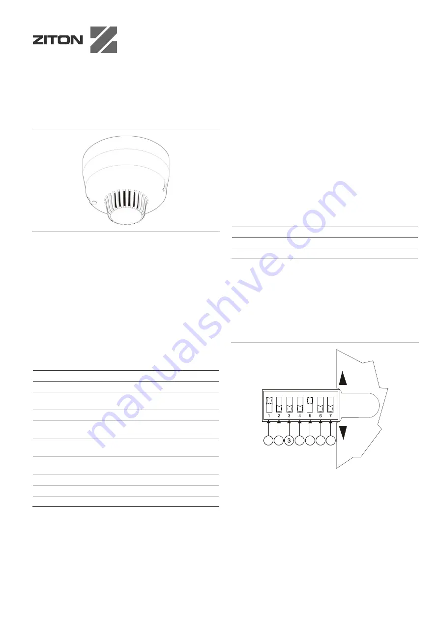
The device is configured using DIP switch SW1, located on the
back of the detector. See Figure 1.
Figure 1: DIP switch SW1
1. SW1-1: Sensitivity 1
2. SW1-2: Sensitivity 2
3. SW1-3: Heat band select
4. SW1-4: Head type (selection 1)
5. SW1-5: Head type (selection 2)
6 SW1-6: Not used
7. SW1-7: Base compatible
O
F
F
O
N
4
2
1
5
6
7


