background image

Installation 

Guide

AL30 & AL40 Series Smart Lock

Version: 2.0

Date: December 2019

Summary of Contents for AL30 Series

Page 1: ...Installation Guide AL30 AL40 Series Smart Lock Version 2 0 Date December 2019 ...

Page 2: ...de may vary without any prior notices to improve the performance of our product v We highly recommend professional installation in order to avoid any additional service charges that may be caused due to the improper installation of the product v On every installation you must perform the initialization process just after the installation of this lock on any door as described in Initialization Proc...

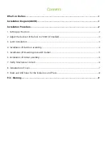
Page 3: ...ust the backset of the lock to 70mm if needed 3 3 Latch Installation 3 4 Installation of Outdoor assembly 4 5 Installation of Mounting plate with Gasket 5 6 Installation of Indoor assembly 6 7 Verify Mechanical Unlock 6 8 Initialization of Lock 7 9 Mark and drill holes for the Strike box and Plate 8 FCC Warning 9 ...

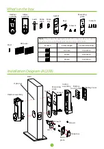
Page 4: ...mm 40 50mm 50 53mm 1 Latch Outdoor assembly Gasket Mounting plate Keys Stud 3M tapes Outdoor assembly Door Gasket Screw C Indoor assembly Battery not icluded Mounting plate Battery Cover Screw A Strike box Strike plate Latch Screw B Optional Note Please use the appropriate set of C screws as per your door s thickness to assure the proper functioning of the locks ...

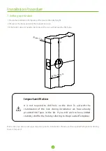
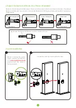
Page 5: ...lock will be fixed by 3M Tapes Important Notice It is not required to drill hole on the door To aid with the stabilization of the lock during installation we have already provided 3M Tapes in the kit If you still wish to have added stability drill for the hole by referring to the provided Templates Make sure your door is set up as required prior to installation Please use the supplied Template for...

Page 6: ... back 3 3 Latch Installation 1 1 2 UP UP Backset is the distance from the edge of the door to the center of the hole drilled on the door The default Backset is 60mm but if you want to change the Backset to 70mm grasp body and twist the Faceplate as shown below Before installing the Latch make sure the Latch Bolt is in retracted Unlocked position and the arrow is facing upwards Secure the Latch by ...

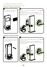
Page 7: ...indle is in the horizontal position as shown 2 Route the cable through the opening the bolt below 3 Attach the Outdoor assembly to the door by inserting it through the Latch Move the Gasket away and fix the Stud on the Mounting plate of Outdoor assembly 1 Make sure the highlighted Spindle is in the horizontal position as shown 2 Route the cable through the opening the bolt below 3 Attach the Outdo...

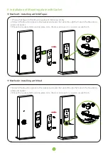
Page 8: ...e Mounting plate to the Gasket and route the cable through the hole on the Mounting plate and Gasket 3 Place the Gasket and Mounting plate on to the door and use 2 C screws to secure them 1 Attach the Mounting plate to the Gasket and route the cable through the hole on the Mounting plate and Gasket 2 Place the Gasket and Mounting plate on to the door and use 3 C screws to secure them ...

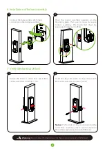
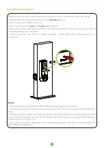
Page 9: ... be positioned in direction of Bolt 7 Verify Mechanical Unlock Rotate the Knob to check that Latch Bolt can be extended correctly or not Insert the Key and rotate to check that Latch Bolt can be extended correctly or not Notice If the Knob or Key cannot control the Latch Bolt correctly please read Installation Procedure carefully and re install the Lock Warning Do not install the batteries until t...

Page 10: ...ock will prompt Complete which means the Initialization process is completed Notice 1 This initialization will clear all the data and detect the appropriate lock direction 2 You can also change the direction of the Lock manually by continuously pressing the Reset Button 5 times 3 If the Installation of the latch is in the opposite direction to the default Lock setting there would be a noise from t...

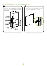
Page 11: ... 2 36 127 29 MM 1 18 127 21 5 MM 215 254 33 MM 1 19 64 Depth 2 MM 10 127 14MM 70 127 8 Make sure that the Strike box is in the level of Latch Bolt then use Installation Template to drill holes Align the Strike box and Plate with the drilled hole and use B screws to secure them ...

Page 12: ...ipment does cause harmful interference to radio or television reception which can be determined by turning the equipment off and on the user is encouraged to try to correct the interference by one or more of the following measures Reorient or relocate the receiving antenna Increase the separation between the equipment and receiver Connect the equipment into an outlet on a circuit different from th...

Page 13: ......

Reviews: