
GND
SEN
BUT
BELL+
BELL-
DC12V
-
+
GND
+12V
Door Bell
%
EXIT
BUTTON
-
+
Alarm
Alarm Power
Exit Button
Door Sensor
Alarm Voltage output
≤
DC 12V
4
.
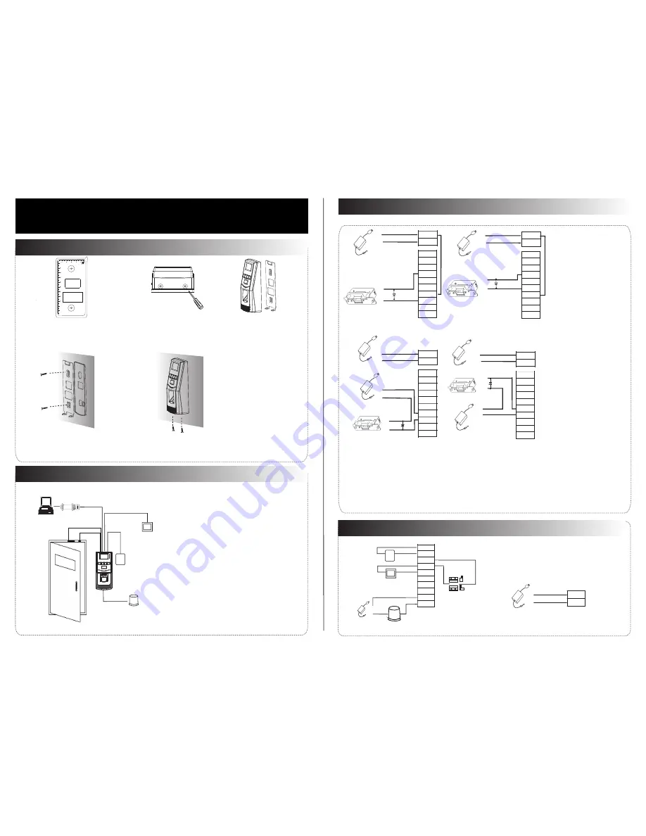
Other
Parts Connection:
5
.
Power Connection:
Input DC 12V, 500mA (50mA standby). Positive
is connected with ‘+12V’, negative is connected
with ’GND’ (do not reverse the polarities).
NC1
NO1
COM1
NO2
COM2
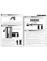
(1) Post
the
mounting
template
on
the
wall, drill
the
holes
according
to
the
marks
on
the template
(
holes
Version: V1.2
Date: March, 2012
(2) Remove
the
screws
on
the
(3) Take
away
the
back
plate
(5) Tighten the screws on the bottom,
plate on the wall according
to
(4) Fix
the plastic pad and the back
RS485
Lock
Sensor
①
③
Alarm
RS485 Converter
②
NC
LOCK
-
+
DC12V
+
NC
LOCK
+
-
NO
LOCK
-
-
FR 107
+
-
+12V
+12V
+12V
+12V
GND
GND
GND
GND
GND
GND
GND
GND
SEN
SEN
SEN
SEN
BUT
BUT
BUT
BUT
BELL+
BELL+
BELL+
BELL+
BELL-
BELL-
BELL-
BELL-
NO
LOCK
-
+
DC12V
+
-
+
-
FR 107
FR 107
-
+
DC12V
+
-
-
+
DC Power
-
+
DC12V
-
+
DC Power
+
-
FR 107
+
Exit Button
⑤
④
Door
Bell
%
BUTTON
EXIT
⑥
for
screws
and
wiring
).
bottom of the device
.
Access
Control
System
Function
(1) If a registered user verified, the device will export
the signal to unlock the door.
(3) If the device is removed illegally, it will output an
(4) External
exit
button
is supported
,
it is convenient to
(5) External door bell is supported.
(2) Door sensor will detect the on-off state. If the door is
unexpected opened or improperly closed, the alarm
signal (digital value) will be triggered.
alarm signal.
open the door inside.
can manage multiple devices.
(6) Supports
RS485 mode to connect with PC. One PC
①:
‘
‘I’: Device output current, ‘
’: Lock voltage,
’: Lock current.
U
LOCK
I
LOCK
(1)
T
he
system
supports
NO LOCK
and
NC LOCK. For example the NO LOCK (normally open at
(2) When the Electrical Lock is connected to the Access Control System, you need to parallel one FR107
power on) is connected with ‘
‘
’
NO’ and COM terminals, and the NC LOCK(normally close at power on )
3
.
Lock
Connection
(1) Share
power with the lock:
U
LOCK
=12V,
I-I
LOCK
>1A
…①
The
distance
between
the
lock
Device
shares
power
with the lock
:
Does
not
shares
power
with the lock
:
A.
=12V I-
≤
1A;
U
LOCK
I
LOCK
B
≠
12V;
. U
LOCK
C. The
distance
between
the lock and
(2) Does not share
power with the lock:
2. Structure and Function
F6 Installation Guide
1. Equipment Installation
NC1
NC1
NC1
NC1
NO1
NO1
NO1
NO1
COM1
COM1
COM1
COM1
NO2
NO2
NO2
NO2
COM2
COM2
COM2
COM2
fix
the
device to
the
back
plate.
Wiring
Hole
Instruction for the Mounting Paper
Before the device is fastened, please
stick the paper to the place where you
want to install it, then make holes and
lay cables according to the mounting
paper.
F6 Mounting Paper
(only for your reference)
Fixing Hole
Fixing Hole
10
11
the
mounting paper
.
is connected with ‘NC’ and ‘COM’ terminals.
Notes:
diode (equipped in the package) to prevent the self-inductance EMF affecting the system,
do not
reverse the polarities.
and the
device
shares Ilock 1A
the device is more than 10 meters.
is equal or less than10 meters.


