background image

Operating Manual

S3 Digital Cutter

Summary of Contents for S3 M-1200

Page 1: ...Operating Manual S3 Digital Cutter ...

Page 2: ...2 Keep it in a safe place for future use Original operating manual Software Firmware version FW1 71 Creation date 05 2019 ...

Page 3: ... 3 6 Personnel requirements 43 3 7 Personal protective equipment 44 3 8 Rules and occupational safety 45 3 9 Conduct in the event of malfunctions 45 3 10 Danger areas 46 3 11 Warnings on the product 49 3 12 Protective devices 51 3 13 Mechanical hazards 55 3 14 Risk of burns 56 3 15 Electrical hazard 56 3 16 Risks arising from the emission of toxic dust 57 3 17 Risks arising from the processing of ...

Page 4: ...ing and rectifying quality problems 156 6 Maintenance 159 6 1 Safe maintenance of the machine 160 6 2 Tools operating and auxiliary materials 160 6 3 Maintenance list for trained operating personnel 164 6 4 Maintenance list for authorized service technicians 166 6 5 Cutter maintenance mode 168 6 6 Service flaps and covers 169 6 7 Visually inspecting the machine for damage 174 6 8 EMERGENCY STOP co...

Page 5: ...Contents 5 8 Modules 209 9 Material handling 211 10 Additional specifications 213 ...

Page 6: ...Contents 6 ...

Page 7: ...s your individual requirements in terms of speed and quality The availability of the most up to date technology thanks to continuous development Our approach Constant and intensive cooperation with experienced users is essential for developing innovative and practical solutions We are therefore grateful for any comments or suggestions on how we can improve Contact Zünd Systemtechnik AG Industriest...

Page 8: ...ions which are numbered consecutively and arranged according to the ring binder tabs The table of contents provides information on the structure of the individual sections Indication of optional accessories There are many optional accessories available for the machine Descriptions of optional additional equipment are labeled in the operating manual with the wording optional Safekeeping of the docu...

Page 9: ...iew for example leads to chapter 2 Product description which contains section 4 Cutter overview Block diagrams and simplified representation Note that all representations are provided for general information and do not necessarily correspond to the latest version of the machine Dimensional information Dimensional information is listed in the SI US units depending on the installation site 1 3 Publi...

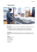
Page 10: ...Introduction 10 ...

Page 11: ...machine 2 1 Important information about the product Tip Tip refers to useful information which enhances the usability and prolongs the service life of the machine or makes the work process significantly easier Tip With tips combined with the sheet we give you usage tips and useful information which can improve the energy efficiency of the machine or optimize its environmental effects Important Usa...

Page 12: ...Product description 12 2 2 Orientation Directions such as right left or front back relate to the operator s view of the machine during operation 1 front 2 rear 3 right 4 left X X axis Y Y axis ...

Page 13: ...CE mark of conformity 15 Frequency 7 UL functional safety 16 Nominal voltage 8 Product name 17 Current consumption 9 Type designation 18 Frequency 2 4 Intended use The cutter system can be used for the following purposes As an output station for CAD CAM data For processing and labeling of materials The intended use and the usage restrictions are also dependent on the available tool and material tr...

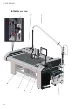
Page 14: ...Product description 14 2 5 Cutter overview ...

Page 15: ...Product description 15 1 Air supply to maintenance units 2 Beam 3 Tool module power supply 4 Extractor 5 Workstation 6 Control panel with optional workstation 7 Vacuum pump 8 Working area ...

Page 16: ...hed to slots 1 and 2 on the module carriage as standard Either an electrically or pneumatically driven marking module can be installed in slot 3 MAM SP MAM SE Tip You can find detailed information in section Handling modules tools on page 88 as well as in the individual operating manuals of your modules and tools 1 Module e g KCM S UM S 2 Tool e g CT UCT EOT POT 3 Tool insert router blade pen ...

Page 17: ...Tool EOT 250 Robust tool with high performance electric drive for processing thick cardboard and leather materials Pneumatic Oscillating Tool POT Powerful cutting tool with large oscillation stroke for hard and tough materials of up to 50 mm thickness Driven Rotary Tool DRT Tool for technically demanding textiles and textile materials The powered rotary knife enables a very high processing speed U...

Page 18: ...rations in corrugated cardboard solid board polypropylene and foil Kiss Cutting Tool KCT Kiss Cutting tool with adjustable pressing pressure for the processing of numerous vinyl materials Universal Routing Tool URT Cost effective routing and engraving tool Creasing Tools CTT1 2 Creasing of various types of materials The pressing pressure is separately adjustable laterally and longitudinally along ...

Page 19: ...etting Optional Minimal Quantity Lubrication MQL for processing soft aluminum alloys 1 kW high frequency spindle for very high processing speeds Tools for use in the RM S HF motor spindle 4040 DC SZ Motor spindle with 1000 W and manual roll pin 2 6 3 Punching perforating Punch and Pricking Module PPM S Combined high performance tool for perforating and punching leather rubber and textile materials...

Page 20: ... tool for perforating leather rubber and textile materials with up to 8 holes per second A marking tool is integrated 2 6 4 Kiss cutting Kiss cut module KCM S KCM S This module cuts films with the highest precision and processing speed without damaging the carrier material ...

Page 21: ...cial leads MAM SE 1 drawing tool electric MAM SP 1 drawing tool pneumatic MAM SPS 1 drawing tool pneumatic MAM SPD 2 drawing tool pneumatic 2 7 Material handling Cutter with static work surface Loading and removal of the processing material on the working surface of the cutter The working surface is protected against damage using a cutting board ...

Page 22: ...shed forward The beam tightens the conveyor belt to the set position The shape of the feeding clamps varies depending on the material to be processed An auxiliary drive is used for larger tables or for transporting heavier processing materials Cutter extensions allow streamlined working The material supply removal is carried out while the cutter is completing the jobs Cutter extensions are availab...

Page 23: ...for the connection of electrically driven tools 2 8 2 ICC camera The ICC camera allows perfect registration in which the exact position of printed material on the processing surface is determined The integrated laser pointer is used as an aid for the precise determination of the reference point Electrically driven tools can also be connected to the camera ...

Page 24: ...assembling modules X X X Torx screwdriver TX10 1 pc Assembling disassembling covers X X X Special guide rail oil 25 ml Oil for the X Y axis guide rails carriage and bearings X X X Lubrication set X axis guide rails 1 pc Oil for the X Y axis guide rails carriage and bearings X X X Staple gun 1 pc Replacing the conveyor belt X Dosing gun KPM 250 ECON 1 pc Replacing the conveyor belt X 19 mm tape dou...

Page 25: ... side of the cutter and is only accessible via a removable cover The power box contains the power supply of the complete cutter and is activated deactivated with the main switch The connection of the individual consumers takes place using software control if required The electronics unit is arranged behind the power box The electronics unit can only be accessed using a special tool The cutter cont...

Page 26: ...splacement using the feeding clamps Y axis module carriage The module carriage is driven by a motor via a toothed belt gear mechanism The design ensures that it works without play and it also minimizes wear on the drive system The module carriage is supplied with control signals and compressed air via an energy chain All drive parts are protected against direct access contamination using covers Z ...

Page 27: ...s 2 11 1 1 Base cutter mm The effectively usable working surface D x E depends on the tool or module Type mm A B B1 C D E M 800 M 1200 M 1600 2086 1542 1942 2342 830 1230 1630 1330 L 1200 L 1600 2556 1942 2342 1230 1630 1800 XL 1200 830 3026 520 1942 1230 2270 ...

Page 28: ... inch The effectively usable working surface D x E depends on the tool or module Type in A B B1 C D E M 800 M 1200 M 1600 82 1 60 7 76 5 92 2 32 7 48 4 64 2 52 4 L 1200 L 1600 70 9 48 4 92 2 48 4 64 2 70 9 XL 1200 32 7 119 1 20 5 48 4 48 4 89 4 ...

Page 29: ...Product description 29 2 11 1 3 Cutter extension CE mm Type Length mm CE0800 875 CE1200 1275 CE1600 1674 M 800 x M 1200 x M 1600 x L 1200 x L 1600 x XL 1200 x ...

Page 30: ...Product description 30 2 11 1 4 Cutter extension CE inch Type Length in CE0800 34 4 CE1200 50 2 CE1600 65 9 M 800 x M 1200 x M 1600 x L 1200 x L 1600 x XL 1200 x ...

Page 31: ...pe Weight lbs max floor load lbs in 2 M 800 M 1200 M 1600 925 1080 1240 L 1200 L 1600 1240 1350 XL 1200 1370 440 2 11 2 3 Material weight kg Type max material weight kg max material weight kg m 2 M 800 M 1200 M 1600 11 16 21 L 1200 L 1600 22 29 XL 1200 27 10 2 11 2 4 Material weight lbs Type max material weight lbs max material weight lbs in 2 M 800 M 1200 M 1600 24 35 46 L 1200 L 1600 49 64 22 ...

Page 32: ...m generator 3 0 KW Current input 3 phases without vacuum generator max 16 A Mains fuse min 1 20 A 1 Applies only to the basic unit The minimum requirements for the mains fuse increase depending on the vacuum generator Vacuum generator For additional data see rating plate original operating manual in chapter Additional specifications While the 1 1 kW vacuum pump is supplied with power via the cutte...

Page 33: ...208 V L1 L2 L3 PE Mains frequency 50 60 Hz Power input 3 phases 2 55 KW Mains fuse min 16 A 4 kW vacuum pump Value Voltage 3 phase 400 V L1 L2 L3 PE Mains frequency 50 60 Hz Power input 3 phases 4 KW Mains fuse min 16 A 12 5 14 5 kW vacuum pump Value Voltage 3 phase 400 V L1 L2 L3 N PE Mains frequency 50 60 Hz Power input 3 phases 12 5 14 5 KW Mains fuse min 32 A 4 6 kW vacuum pump Value Voltage 3...

Page 34: ...V L1 L2 L3 PE Mains frequency 50 60 Hz Power input 3 phases 1 9 KW Mains fuse min 50 A 2 11 4 Environmental conditions Value Operating temperature 10 C to 35 C Storage temperature 20 C to 55 C Relative humidity 10 80 non condensing 2 11 5 Compressed air supply 2 11 5 1 Compressed air connection requirements Important The compressed air connection must fulfill the following requirements Air purity ...

Page 35: ...se connection max air consumption l min Electric Oscillating Tool EOT 250 70 Universal Routing Tool URT 60 Marker modules MAM SP MAM SPS MAM SPD 20 Router modules RM S 40 Sheet feeder feed 150 Sheet feeder removal 150 Base machine vacuum elements 0 6 0 6 1 0 covered with base consumption Compressed air regulator P3 Air pressure MPa Maintenance unit House connection max air consumption l min Minima...

Page 36: ...Value Unit Speed in vector direction 1 14140 04 55 67 mm sin s Max acceleration in vector direction 1 14 14556 9 m s 2 in s 2 max permissible printing force of the printhead creasing 100 N 1 depending on the module equipment and cutter size 2 11 7 Emissions Noise emission Cutter noise emission 75 dB A Depending on the cutting technology used the machined material the vacuum generator and the envir...

Page 37: ...rated in a commercial environment This equipment generates uses and can radiate radio frequency energy and if not installed and used in accordance with the instruction manual may cause harmful interference to radio communications Operation of this equipment in a residential area is likely to cause harmful interference in which case the user will be required to correct the interference at its own e...

Page 38: ...Product description 38 ...

Page 39: ...e art at the time of delivery However the equipment may pose dangers if the safety instructions in this guide are not observed and implemented 3 2 Proper use Proper use of the machine is essential for its safe operation The equipment supplied is listed and labeled and indicates the usage possibilities of the machine The machine is intended for use as an output device for CAD CAM data for labeling ...

Page 40: ... is not intended for use with the material or the machine Operating the machine without the designated protective devices Use of modified module and tooling systems Installation of spare parts and use of accessories and resources not approved by the manufacturer Constructional changes to the machine without subsequent risk assessment Failure to observe the maintenance requirements Failure to react...

Page 41: ...n life threatening injuries Warning The safety instruction Warning refers to a dangerous situation refers to operational and service risks warns of adverse health effects or even life threatening injuries Caution The safety instruction Caution refers to a dangerous situation refers to operational and service risks warns of minor reversible injuries and other serious material damage and consequenti...

Page 42: ...he energy efficiency of the machine or optimize its environmental effects Important Usage tips and important information Structure of the hazard warnings 1 Hazard symbol with the corresponding signal color 2 Signal word corresponding to the danger resulting from the situation 3 Description of the danger 4 Description of the consequences which could result from this hazardous situation 5 Possible a...

Page 43: ...rding to the maintenance schedule Notifying the manufacturer of any accident involving the machine that results in serious injury or substantial material damage Decommissioning the machine immediately if defects arise that affect its operational safety Areas of responsibility of the operating and service personnel Wearing the required personal protective equipment Halting operation immediately in ...

Page 44: ...quipment comprises of Work clothes service personnel protective goggles operating and service personnel To provide protection from particles during machining To protect the eyes from dangerous radiation To protect the eyes from chemicals Protective gloves where injury is possible due to burns sharp or pointed objects Chemical resistant protective gloves where injury is possible due to chemicals cl...

Page 45: ...y service technicians authorized by the manufacturer are permitted to install commission maintain and repair the machine Before carrying out any maintenance repair and modification work Switch off the machine using the main switch and secure it with a padlock Prevent the machine being switched on inadvertently by removing the mains supply cables to the power box several mains connections available...

Page 46: ... or the active area of the drive system Never reach into this work area during processing 3 10 2 Danger area during initialization Caution Risk of injury during manual initialization of the tool The safety devices are not active during manual initialization Do not reach into the danger area during manual initialization ...

Page 47: ...ked danger area during the initialization phase 3 10 3 Danger area during cleaning Caution Risk of injury when cleaning the machine Blades router bits and punching inserts have very sharp edges which are sometimes hidden by moving equipment spring loaded gliding disc Before starting to clean remove all modules and tools from the module carriage Switch off the machine with the main switch and secur...

Page 48: ...Safety 48 While cleaning work is being performed attach a sign that says DO NOT SWITCH ON that is prominently displayed on the main control panel of the machine 1 Danger area ...

Page 49: ...nd tools are illustrated in the respective operating instructions No Description Variant 1 CE Variant 2 ANSI 1 Mandatory sign Wear protective gloves Art no 5800412 50 mm Art no 5801106 65 mm 2 Mandatory sign Wear eye protection Art no 5800467 50 mm Art no 5801058 65 mm ...

Page 50: ...t no 5800342 50 mm Art no 5801059 65 mm 4 Warning sign Electrical hazard Art no 5801338 50 mm Art no 5802331 95 mm 5 Warning sign Electrical hazard Art no 5200367 110 mm Art no 5200367 110 mm 6 Warning sign Laser beam Art no 5811418 50 mm Art no 5800344 25 mm Art no 5811418 50 mm Art no 5801062 40 mm ...

Page 51: ...ion The beam may cause serious injuries in case of a collision Note that the high level of kinetic energy of the drive results in a significant braking distance Light barriers are no guarantee against injuries The protective system consists of light barriers on the bar ends and on the module carriage The machine is stopped automatically if the light barriers detect an obstacle ...

Page 52: ... the light barriers of obstacles Acknowledge the error message on the control panel Tip If the Z axis is in the upper or lower position when the safety device is triggered it is now raised to the park position 3 12 2 Control panel Malfunctions are shown on the LCD display An acoustic signal sounds in the event of an error or light barrier interruption or activation of an EMERGENCY STOP control dev...

Page 53: ...circumstances Note To unlock an activated EMERGENCY STOP control device after restoring operational safety turn the switch clockwise see Reset EMERGENCY STOP control devicesReset EMERGENCY STOP control devices on page 82Reset EMERGENCY STOP control devicesReset EMERGENCY STOP control devices ...

Page 54: ...nchornised movements are stopped Units that are not safety relevant or important for the operation of the machine remain switched on 3 12 5 Shutdown in the event of overload The machine automatically shuts down if an axis X Y T Z becomes blocked or overloaded Effects for the cutter The drive motors beams module carriers are braked to a standstill and are then disconnected from the energy supply Th...

Page 55: ...nds on side covers Do not lean with the torso on the work surface Avoid untied long hair and loose clothing and ties These precautions specifically apply if the cutter can be switched into ONLINE operating mode by the CAD CAM system 3 13 2 Hazards from foreign bodies Caution Injury risk due to objects being ejected Foreign bodies on the table plate are collected by the beam or the module tool modu...

Page 56: ...res during processing Possible consequences Burning injuries to the limbs Precautionary measures Allow workpieces to cool down before removal Wear suitable protective gloves when removing freshly processed workpieces Allow tools router blade to cool before removing them 3 15 Electrical hazard Warning The machine is operated with a mains voltage of 400 208 V and a mains frequency of 50 60 Hz Possib...

Page 57: ...s extraction systems that comply with the following regulations the extraction of hazardous dusts with MAK values up to 0 1 mg m 3 and wood dusts conforming to dust class M the extraction of dusts conforming to dust class H 3 17 Risks arising from the processing of toxic materials materials hazardous to health Warning Risk of poisoning from emissions when processing toxic materials Processing such...

Page 58: ...ironment Safety regulations and protective measures Dispose of waste materials in accordance with current national environmental protection regulations In case of doubt check on the appropriate disposal methods with your local collection point or recycling center Collect different chemicals in separate containers 3 19 Handling and storage of chemicals Warning Cleaning agents and operating material...

Page 59: ...gear protective gloves goggles mouth guard etc when handling chemicals Explanation of the hazard label Hazard label for very toxic or toxic substances Hazard label for hazardous substances or irritant materials Hazard label for irritating substances ...

Page 60: ...dling of chemicals Important Dispose of chemicals in accordance with national regulations Follow the manufacturer s instructions MSDS Store chemicals in tightly closed containers in a cool dry place between 5 C and 30 C Protect the containers from heat and direct sunlight Provide good ventilation including at floor level Store chemicals in accordance with local regulations Keep containers tightly ...

Page 61: ...sing and if necessary do not process it If necessary adjust the extraction to the required regulations Observe the following safety rules and countermeasures Find out the locations where fire extinguishers are kept and familiarize yourself with their use and operation The adjacent sign indicates the location of a fire extinguisher Do not use inflammable cleaning agents to clean the cutter Store al...

Page 62: ...he human eye in case of short term exposure 0 25 s class 2 laser The ICC camera with laser pointer or the laser pointer are switched on together with the cutter By design the laser beam is directed down onto the material Safety instructions Do not look into laser beam If a laser beam hits your eye close your eyes or turn away immediately Keep in mind that certain medications or consuming alcohol m...

Page 63: ...ng functions Marking substances that are toxic and harmful to the environment Instructions for disposal of harmful substances Warning against disposal with domestic waste or environmental pollution caused by hazardous substances and objects contaminated with such substances Measures for disposal Zünd cutters correspond with the requirements of the German Electrical and Electronic Equipment Act and...

Page 64: ...Safety 64 ...

Page 65: ...ne 4 1 Safe working practices Danger Operating errors or negligence can put human lives at risk as well as causing serious damage to the machine The machine is fitted with safety devices to minimise risk However these safety devices cannot guard against damage as a result of operating errors or negligent working practices Observe the safety requirements from Chapter Safety on page 39 and the situa...

Page 66: ...Controls and operation 66 4 2 Controls 4 2 1 Overview 1 Rear EMERGENCY STOP control device 2 Control panel and workstation optional 3 Maintenance units dependent on cutter configuration ...

Page 67: ... Soft keys 9 STOP key 3 Navigation keys 10 VAC vacuum key 4 Number block and function keys 11 Router on off key optional 5 Tool up down key 12 Front processing approval optional 6 Travel keys 13 Switch on front vacuum optional 7 SHIFT key 14 EMERGENCY STOP control device ...

Page 68: ... control devices as standard They are located as follows 1 x on control panel 1 x on side support cover on left Danger Risk of injury due to inaccessible EMERGENCY STOP control device Machines with inaccessible EMERGENCY STOP control devices are not safe for operation The machine cannot be stopped promptly in hazardous situations Ensure that all EMERGENCY STOP control devices are easy to access an...

Page 69: ...remains locked in the off position To unlock an activated EMERGENCY STOP control device after restoring operational safety turn the switch clockwise see Reset EMERGENCY STOP control devices on page 82 4 2 4 Maintenance unit The maintenance unit adjusts the air pressure to the switching of the vacuum elements various modules and options 1 Maintenance unit POT 2 6 Air pressure setting 3 5 Stopcock 4...

Page 70: ...Controls and operation 70 The maintenance unit is preset and adjusted Check the air pressure setting at regular intervals The setting values can be found in the chapter Basic unit compressed air supply ...

Page 71: ...ntrols and operation 71 4 2 5 Interfaces The machine has data exchange interfaces These are attached to the electronics unit 1 LAN 2 not used 3 USB host not used 4 Status and error display 5 COM 1 6 COM 2 ...

Page 72: ... Help Help texts are available for important menu entries In order to display a help text mark the required menu and press the key 4 3 3 Info menu Within the menu the Info menu can be activated with the key The info menu also works in online dialog and when an error message is displayed Tab Information Assignment Information on the module carriage Module Information about the module Position Speci...

Page 73: ... that are called up using function keys pop ups The system changes back to the previously active menu when a pop up or a dialog box is closed 4 3 5 Layout Symbol Description Menu Blocked menu user level Command execute function Display of a value 4 4 Menus and functions The cutter has a multitude of functions The current menu number and the current menu are displayed in the header 4 4 1 Navigation...

Page 74: ... immediately after entry An exception to this rule are safety relevant commands e g automatic startup Confirm the selection with OK or cancel with ESC 4 4 4 Direct selection of menus Each menu and each function is allocated a unique menu number It is possible to switch between menus by entering the menu number Two figure menu numbers 10 11 are displayed lower down Before entering two digit menu nu...

Page 75: ...irm the selection with OK or cancel by pressing ESC Resetting a function key to the factory settings To change the function keys at least the User level on page 76 Operator is required A Change to the 6 5 Function keys menu B Enter the numbers 1 8 for the respective function key F1 F8 C The function key selection window opens D Press the DEF key to load the factory settings E Confirm the selection...

Page 76: ...o menus and functions is blocked depending on the user level The user levels have a hierarchical structure This means that the next highest user also has the access rights to the menu functions of the subordinate user User level Description Users 1 3 All menus and functions needed for the operation of the machine are accessible Operator Simple uncomplicated adjustments can be made Service Cutter s...

Page 77: ... A Change to the 4 3 Start user menu B Select the desired user Results The selected user level will be active the next time the cutter is started 4 6 3 Changing the password for user levels 2 and 3 Tip The passwords for user levels 2 and 3 can be changed in the Operator user level or higher A Change to the 4 4 Change password menu B Select the user C Enter the new password for the user ...

Page 78: ... via the control panel or if the control panel is defective via the Status and error display on the electronics unit 4 7 2 1 Error display on the operating unit The error code is made up of a multi digit uniquely allocated combination of numbers and letters The signal word before the error code indicates how serious the error is 1 Signal word 2 Error codes 3 Error description Signal word Error cod...

Page 79: ...tor Display of the error is complete and another error follows 6 Error code 3 Display of the next error code 7 Conclusion Display of the group has been completed 4 7 3 Error display If a number of errors have occurred then the first error of this sequence is always shown on the display of the operating unit All errors which have occurred after confirmation of the last error are collected together ...

Page 80: ...utter control compressor PC L2 16 A type C Extractor various options L3 16 A type C Auxiliary drive router converter A Stop work B Remove the outer cover of the power box see Remove the power box cover A10 A21 C Push the switch lever upwards when the automatic circuit breaker is triggered Option Description The automatic circuit breaker triggers again Shut down the cutter Report the defect to your...

Page 81: ...s are performed in accordance with the maintenance schedule Before starting up the machine each day perform an inspection of the machine and check the following Visually inspect the machine for damage Remove local dirt caused by processing materials and dust Remove objects from the work surface and the beam Remove objects from the work surface and the beam Check whether all maintenance and service...

Page 82: ...RGENCY STOP control device remains locked in the off position Effects on the options connected to the cutter All potentially hazardous movements are stopped Units that are not safety relevant or important for the operation of the machine remain switched on 4 9 2 Reset EMERGENCY STOP control devices A Restore operational safety B Turn the EMERGENCY STOP control device clockwise to unlock C Acknowle...

Page 83: ...ssage on the operating unit C Bring the machine into ONLINE mode to continue processing 4 10 Start up 4 10 1 Switch on the machine 1 Main switch off position 2 Main switch on position Switch the main switch to the ON position Pos 2 Results The cutter switches on The start page appears on the display ...

Page 84: ... of the machine Press the function key on the operating unit Results The cutter is initialized 4 10 3 Switching off the machine A Switch the cutter to OFFLINE mode B Select the 12 Turn off cutter function from the menu or press the key combination SHIFT C Confirm the dialog with Yes D The start page appears on the display E Switch off the cutter with the main switch If necessary secure the main sw...

Page 85: ... mode to another mode current operating status input 4 11 2 OFFLINE Caution Risk of injury due to automatic start up of the cutter In OFFLINE mode the cutter receives commands from the operating software These commands can be used to switch to ONLINE mode Activate the STOPPED operating mode during breaks Always perform set up work on the machine in STOPPED mode After the cutter is switched on OFFL...

Page 86: ... received but they are not processed Even commands from the operating software e g to change to the ONLINE operating mode are ignored A red illuminated LED on the ONLINE key indicates that the operating mode STOPPED is active 4 11 4 ONLINE Commands are received and processed in this operating mode A green illuminated LED on the ONLINE key indicates that the operating mode ONLINE is active ...

Page 87: ...signment of the keys corresponds to the direction of travel Pressing the SHIFT key at the same time will make the module carriage move faster Pressing a travel key in the X and Y direction at the same time will make the module carriage move diagonally If one or more travel keys are pressed in ONLINE mode then all movement is stopped and switches to the OFFLINE status ...

Page 88: ... recognized by the cutter control unit Tools on the other hand do not have automatic recognition and must be manually allocated to a module Tool specific parameters initialization moving speeds acceleration are saved to the corresponding tool and can be called up again at any time ...

Page 89: ...Controls and operation 89 4 13 1 Module tool tool insert 1 Module e g KCM S UM S 2 Tool e g CT UCT EOT POT 3 Tool insert router blade pen ...

Page 90: ...Controls and operation 90 4 13 3 Inserting replacing the module ...

Page 91: ...13 3 1 Module carriage 1 Module carriage slot 1 2 Module carriage slot 2 3 Module carriage slot 3 reserved for marking module MAM SE MAM SP 4 Pneumatic connections 5 Guide pins 6 Laser pointer with electrical connections optional ...

Page 92: ...er the module until the stop D Screw the module to the module carrier with the 4 mm Allen key 2x Results The module is now mounted and is located by the software 4 13 3 3 Removing the module A Select 1 5 1 Change module tool The module carriage moves to the module change position B Unscrew the module fixation with the 4 mm Allen wrench 2x C Raise the module and remove from the guide pin ...

Page 93: ...n order to check the settings This function can only be carried out in the main menu The active module can for example be used as a pointer to define the vacuum width or the reference point Module Key combination Module 1 Shift Module 2 Shift Module 3 Shift ICC camera Shift 8 Laser pointer Shift 9 ...

Page 94: ...abels are supplied with the equipment 4 13 6 Tool manager The tool manager is a user interface to handle tools in combination with a universal module UM A sensor on the module detects the presence of the inserted tool The tool manager helps you carry out the following activities Inserting a tool Attach select a tool Initialize a tool ...

Page 95: ...to the menu for manual or automatic initialization After initialization the parameters are saved The tool manager closes and the main menu appears 3 Confirm the tool selection with OK The previously used parameters for this tool will continue to be used 4 13 6 2 Creating a new tool The tool is inserted in the module A Select 1 1 1 1 Select tool in the menu B Select NEW C The Create new entry pop u...

Page 96: ...module are listed C Select the tool inserted 4 13 6 4 Deleting a tool A 1 1 1 1 Select tool All tools already assigned to this module are listed in the tool type dialog B Select the tool C Delete the selected tool with Delete 4 13 6 5 Saving tool specific settings Use ESC to change to the main menu Results The tool specific settings that have been made are automatically saved ...

Page 97: ...l of the laser pointer or the ICC camera optional A port is allocated to each individual connection which must be assigned via the cutter control unit before the initial commissioning of the respective tool Pneumatically driven tools are connected to the pneumatic connections on the module carriage 4 13 7 1 Connecting electrically driven tools 1 Connection 1 port 1 black e g EOT 2 Connection 2 por...

Page 98: ...ing a maintenance unit The air supply is connected to the local installation or supplied via a compressor The connection data or the connection procedure can be found in the operating manual for the respective tool module Note Always use a protective plug to protect connection P4 from dirt in the air supply If particles of dirt get into the tool it will be damaged For more information see Mount pr...

Page 99: ...Controls and operation 99 P2 Compressed air connection P2 e g sealing air EOT 250 P4 Compressed air connection P4 e g POT ...

Page 100: ...onnection P4 from dirt in the air supply If particles of dirt reach the tool it will be damaged 1 Protective plug 2 Interface unit P1 Compressed air connection P1 P2 Compressed air connection P2 P4 Compressed air connection P4 Procedure A Press down on air pressure connection coupling P4 B Place the protective plug in the coupling ...

Page 101: ... E g UCT After initialization three tool positions can be moved to with Pos Position Description Key Signal A Parking position Moves to the highest position on the Z axis B Up position Zero point up position C Down position Zero point Down position Z offset ...

Page 102: ... cutter is fitted with Standard and Foil plastic perforated plates the width of the vacuum is continuously adjustable In cutters with Leather plastic perforated plates the vacuum width is not adjustable The strength of the hold down is dependent on the vacuum generator used Depending on the size and the power requirement either a vacuum turbine or a gas ring vacuum pump is used for the S3 series P...

Page 103: ...Controls and operation 103 Plastic perforated plate Adjustable vacuum range Leather no ...

Page 104: ...o achieve optimum material hold down during the processing procedure 1 Processing material 2 Covering the excess vacuum area A If possible position the material to be processed at the zero point of the work surface B Use a tarpaulin or an airtight material to cover the excess vacuum area ...

Page 105: ...ion on page 126 B Select the 1 8 3 4 Define vacuum range function Results The vacuum range has been defined Entering the vacuum width A Use the key to change to the 1 8 Hold down functions menu B Enter the width of the vacuum under 1 8 3 2 Vacuum width C Press OK to confirm Results The vacuum range has been defined Checking the range A Use the key to change to the 1 8 Hold down functions menu B Se...

Page 106: ... and operation 106 The pointer is positioned over the defined vacuum width 4 14 3 Switching on and off A Use the key to change to the Fixation menu3 1 1 B Switch the vacuum on and off with Vacuum on off 3 1 1 2 ...

Page 107: ...he work surface through suction The processing material is held down against the work surface and does not move during processing Air cushion If Blowing is activated blowing is switched on before a feed instead of suction An air cushion is created between work surface and processing material There are two variants to choose from This air cushion remains in place throughout the entire feed and thus...

Page 108: ...ls and operation 108 Air cushion before or during the material transport Menu Setting 1 7 1 17 1 Air cushion Switch short blast before material transport on or off 1 7 1 5 Vac beh immer fixiert zeitoptimiert ...

Page 109: ... 4 40 Level 5 50 Level 6 60 Level 7 70 Level 8 80 Level 9 90 Level 10 max Tip Observe the following advice to achieve a best possible material hold down Select a vacuum level appropriate for your material The material can be damaged if the vacuum is too high e g corrugated cardboard Cover open vacuum areas This allows you to select a lower power level Only use level 10 for materials that are air p...

Page 110: ...ollowing a completed work process The conveyor belt is gripped and fed using two clamping elements while the processing material is held down with feeding clamps a feed guide rail The arrangement and activation of the feeding clamps is determined based on the processing material If a feed guide rail is used then all feeding clamps are activated in fixed positions ...

Page 111: ...ew for fixing the feeding clamps B Position the feeding element pay attention to the hose length C Tighten the screw for fixing the feeding clamps Activating deactivating feeding clamps A Turn the compressed air on off screw clockwise to deactivate the vacuum element B Turn the screw anti clockwise about three rotations to activate the vacuum element ...

Page 112: ...D Loosely screw the feeding bar to all feed elements using the supplied self locking screws E Tighten the fixation of the feed elements F Switch the cutter on with G Lower 1 7 2 3 Lower feed clamps and raise 1 7 2 3 Lift feeding clamps the feeding bar several times for inspection purposes 4 15 3 Feed The following parameters can be set in the cutter menu Speed Acceleration Feeding mode Function of...

Page 113: ...ves to the starting point of the feed The feeding clamps are lowered and the conveyor clamp elements grip the conveyor belt A feed is executed If the feed length is greater than the length of the work surface this process is repeated until the specified length is reached Manual feed A Lower the feeding clamps 1 7 2 3 Lower feed clamps B Carry out a feed using the travel keys C Raise the feeding cl...

Page 114: ...peration 114 4 16 Automatic tool initialization AKI optional Tip Manual initialization is described in the operating manual of the relevant tool See chapter Tools 1 AKI holder on the table plate 2 AKI 3 Storage tray ...

Page 115: ... gliding shoe EOT Electric Oscillating Tool POT Pneumatic Oscillating Tool DRT Driven Rotary Tool URT Universal Routing Tool position mode SCT Scoring Cutting Tool RM S Routing modules The following tools are not compatible with automatic tool initialization UCT Universal Cutting Tool with fixed gliding shoe CTT1 Creasing Tool type 1 CTT2 Creasing Tool type 2 SDT Drawing Tool URT Universal Routing...

Page 116: ...atic tool initialization is flat on the cutting surface conveyor belt Adjust the height if necessary A Rotate the adjusting screw counterclockwise B Place the AKI on the cutting surface C Adjust the inclination with the adjusting screw so the AKI rests flat on the cutting surface ...

Page 117: ...down position 1 1 1 2 3 Up Z pos The up position defines the distance between the zero point and the raised tool Select this value according to the material and its folding properties A short distance between processing material and raised tool generally means a shorter processing time 1 1 1 2 4 Down Z pos The down position defines the cutting depth of the tool into the cutting routing base This i...

Page 118: ...carriage leaves the AKI area C Pull the AKI out of the pickup station D Position the AKI in the AKI guide and make sure the AKI rests flat on the work surface E Follow the instructions on the cutter control unit Results The tool is positioned via the AKI and the initialization process is started The tool is initialized at the exact height of the cutting and milling base and the determined value is...

Page 119: ... Important Tandem operation is only available if the cutter is fitted with the tandem vacuum system option In addition to the vacuum zones the vacuum plate is subdivided into two front and rear sections which act independently of one another 1 Front working area 2 Rear workspace ...

Page 120: ...the front working area 1 6 1 1 1 Front off Switch off the vacuum air cushion for the front working area 1 6 1 1 1 Front vacuum Vacuum pre selection 1 6 1 1 2 Front air cushion Air cushion pre selection 3 1 1 4 Rear status Indicates whether switched off in front working area or whether a vacuum or an air cushion is present Switch on the vacuum air cushion for the rear working area 1 6 1 1 4 Rear of...

Page 121: ...ntrols and operation 121 4 17 1 2 Controls description 1 Front working surface 2 Center of table 3 Rear working area 4 Key rear processing approval 5 Key switch on rear vacuum 6 Key switch on front vacuum ...

Page 122: ...fter being placed on the working area The key lights up when the vacuum is switched on Processing approval The key is lit when the processing approval has been granted As soon as processing is finished in the other working area the working surface for which approval has been granted will be processed No approval granted After loading press the processing approval key This indicates to the cutter t...

Page 123: ... operation 123 The signals are installed on both working surfaces When the signals for a working surface light up green material can be loaded and unloaded on the working surface concerned 4 17 1 3 Tandem operation ...

Page 124: ... In this process the KCM S is positioned precisely above the cutting strips and a clean through cut is made in Position mode 1 Kiss Cut Module KCM S 2 Cutting strips Menu Function 3 6 2 Cut off The KCM S is positioned above the cutting strips and a through cut is performed 1 7 2 7 Cut feed If a KCM S is installed this command is used to perform a feed from the current module position up to the cut...

Page 125: ...ilm end sensor A film end sensor stops the operation automatically when the material end is reached Menu Function 1 7 1 12 1 Material sensor Switches the film end sensor on off 1 7 1 12 2 Status Displays the status of the film end sensor ...

Page 126: ... Connection 3 port 3 1 1 See Connecting powered tools 4 19 2 Pointer selection Optionally either the current tool or the laser pointer can be set as the pointer The position of the pointer is used to define for example the reference point or the vacuum width A Select the 1 5 2 1 1 Pointer type function B Select the laser pointer or tool Results The pointer is selected and active ...

Page 127: ...t A reference point can be defined on the processing surface of the cutter This reference point is the starting point for the processing procedure and corresponds to the zero point of the processing file 1 Reference point 2 Zero point X Y axis cutter ...

Page 128: ... the 2 1 1 3 Define a reference point function B Use the travel keys to move to the required reference point on the workspace Press OK to confirm Results The reference point is saved for the duration of time that the cutter is switched on This reference point now applies as the starting point for the processing of material ...

Page 129: ...4 Fixing screw 5 Stop 6 Laser beam exit 7 Camera lens 1 See Connecting powered tools on page 97 4 20 2 Registration marks The ICC camera is used to determine the position of printed material on the processing surface using software The material has the same registration marks as those in the processing file Recording of the registration marks is software dependent ...

Page 130: ...mark requirements in case of reflective materials Color the image evaluation in the front end software can also use the color to detect the registration mark along with the shape Diameter So that the reflective camera lens is not detected as a registration mark the diameter of the registration mark should be selected larger than17 mm0 7 inor smaller than14 mm0 5 in ...

Page 131: ...ation 131 4 20 3 Setting the camera position 1 Fixing screw 2 Spacer 3 Material 4 Cutting board A Open the spacer B Release the fixing screw C Lower the camera until the stop D Fasten the fixing screw E Open the spacer ...

Page 132: ...not monitored by safety devices Do not reach into the active area of the cutter during operation Protect non occupied slots with slot protective plates On the one hand the slot protective plate is used as a safety device and on the other it is used to protect a free module slot from contamination 1 Protective slot plate ...

Page 133: ... s operating status warnings and any errors Signal color Operating state meaning effect STOPPED Red Error Cutter stops OFFLINE Cutter stops Yellow Warning Machining continues a warning appears on the operating unit Green ONLINE Blue User action required on control panel User action in Zünd Cut Center required ...

Page 134: ...Controls and operation 134 ...

Page 135: ... Zünd recommends using Zünd Cut Center ZCC as the processing software The ZCC material database contains a multitude of materials the optimum processing methods and the processing parameter required for it Each material possesses specific properties that have to be observed during processing The Zünd modular tool concept offers the right processing method for every material Processing with drag kn...

Page 136: ...ry sharp pointed blades should only be used to cut small radii The feed speed must be reduced to achieve a good quality cut Flat knife e g Z43 Pointed knife e g Z20 High processing speed Large radii straight or large parts Low processing speed Small radii or small parts 5 2 1 2 Drag knife Drag knives are used in combination with non powered tools UCT SCT PPT VCT KCT Maximum processing speed Cheap ...

Page 137: ... Z50 Very high processing speed Suitable for large radii straight or large parts Recommended for breathable materials such as textiles carbon fiber glass fiber etc Very large overcut 5 2 2 Knife types Depending on which tool the knife is used in a distinction is made between the following knife types Drag knife this knife is used in non powered tools such as UCT VCT SCT PPT KCT KCM S Oscillating k...

Page 138: ...ional specifications provided for each blade contain a list of the materials for which it can be used 5 2 3 2 Cutting angle The cutting angle has a major effect on the cutting force With drag knives a narrow cutting angle means smaller drag forces However this has the disadvantage of creating a larger overcut Drag knife Oscillating knife flat Oscillating knife pointed 5 2 3 3 Maximum cutting depth...

Page 139: ...Tips for cutting 139 T Material thickness Z Set depth TM Cutting depth material thickness t set depth z ...

Page 140: ...The overcut distorts the cutting paths For cuts with a low margin of error Zünd recommends choosing a knife with a lower overcut Overcut information can be found in the additional specifications for each knife Drag knife Oscillating knife flat Oscillating knife pointed 5 2 3 4 1 Calculating the overcut Depending on the cutting depth the blade geometry will produce a different level of overcut This...

Page 141: ...Material thickness Z Set depth TM Cutting depth material thickness t set depth z x1 Pre cut x2 Post cut Sample calculation Z20 Sample calculation Z11 Formula x 1 2 0 11 x TM x1 2 0 58 x TM Cutting depth TM 10 2 mm TM 5 2 mm Pre cut x1 2 322 mm x1 3 016 mm Post cut x2 3 016 mm ...

Page 142: ...he cutting result are effected by the acceleration quality and speed selected 5 4 1 Quality and acceleration Above all the output quality is defined by the quality and acceleration settings If a high quality is required it is recommended to select quality level 1 high If the result is still not satisfactory the acceleration can additionally still be reduced from 4 to 3 2 or 1 If the quality is les...

Page 143: ... cutting contour High speeds can only be reached in sufficiently long straight sections or sufficiently wide radii If the cutting or routing process allows it it is recommended to leave the maximum speed at 1 m s If the cutting process requires a very low speed and the radii are not too tight a reduction of the speed is recommended Recommended acceleration level depending on the speed Speed mm s A...

Page 144: ...clamped at an angle If the blade does not lie exactly at the zero point a cut is produced that runs parallel to the original cutting path 1 Contour as per processing file 2 Effectively cut contour due to blade clamped at an angle Y1 Deviation of the blade to zero point ...

Page 145: ...e rotational axis of the blade will be displaced This results in the following quality defects The start and end point of the cutting path do not match up Curves are cut inaccurately 1 Contour as per processing file 2 Effectively cut contour due to blade displaced from the turning center X1 Deviation of the blade to the turning center ...

Page 146: ...values set to 0 Cutting diagram once the alignment process has been successfully completed Y correction correcting contour error caused by blade clamped at an angle During Y correction the cuts are moved until the respective parallel cuts are on one line Start the 1 1 1 4 5 Test cut function Measure distance a mm in of the parallel cuts and calculate as follows Option 1 Line 1 has to be moved to t...

Page 147: ...oint line 1 to penetration point line 2 of the opposite cuts and calculate as follows Option 1 The distance between the penetration points is greater than the distance between the ends of the cuts X existing X correction value b 2 Option 2 The distance between the penetration points is smaller than the distance between the ends of the cuts X existing X correction value b 2 Result The penetration p...

Page 148: ...is usually generated at the penetration point when blades have two cutting edges e g Z11 This can be avoided by using blades with only one cutting edge At the tip of the blade the end point of the straight lines corresponds to the target cutting outline The shape and dimensions of the blade lead to an overcut on the material top side ...

Page 149: ...9 5 5 5 Cutting from 2 sides Overcut Optimized Cutting of corners with overcut An overcut can be avoided if the cutting path is divided and cutting is carried out from 2 sides The disadvantage is a longer production time ...

Page 150: ...ial corresponds to the desired contour as per the processing file Top side The contour cut on the top side of the material contains the contour error resulting from the overcut Schematic representation 1 Rotational axis of the tool 2 Desired contour contour cut on the underside 3 Contour cut on the top side with contour error X overcut ...

Page 151: ...g path X correction x 2 Underside x 4 mm X correction 2 mm The contour cut on the underside of the material has a low margin of error Top side x 4 mm X correction 2 mm The contour cut on the top side of the material has a low margin of error Schematic representation 1 Rotational axis of the tool offset by the X correction 2 Desired contour 3 Contour cut on the top side with contour error 4 Contour...

Page 152: ...ting edge cuts the material surface The Z20 pointed oscillating knife and Z11 drag knife are used as examples to illustrate how to calculate the overcut based on the blade you are using and the material you are cutting Example Z20 Example Z11 1 Material 2 Cutting board T Material thickness Z Set depth TM Cutting depth material thickness t set depth z x1 Pre cut x2 Post cut The cutting depth TM is ...

Page 153: ... mm Performing X correction with X 2 Only perform the X correction with the value X 2 after the XY correction has already been performed once Open 1 1 1 4 2 Correct X Enter the existing value and the calculated value X 2in the field1 1 1 4 2 Correct X Perform a 1 1 1 4 5 Test cut and recalculate the correction value if necessary ...

Page 154: ...ns Tool Stroke A mm Frequency f Hz Stroke speed zv m s EOT 0 5 0 5 300 0 471 sine motion EOT 1 0 1 0 300 0 943 sine motion EOT 250 2 5 250 1 963 sine motion POT 8 0 180 2 880 sawtooth curve Stroke and frequency decrease with increasing load Tip Note the following when selecting the tool The higher the frequency the higher the cutting speed as a function of the perforation of the material The highe...

Page 155: ...Tips for cutting 155 5 6 2 Calculation of maximum speed for EOT POT Z16 Z42 ...

Page 156: ...tting contour Select a blade which is appropriate to the material material thickness and cutting contour For help with selecting the right one refer to the Zünd accessories catalog Cutting distortion of curves due to blade overcut Due to the geometry the blade produces a large overcut Select a blade which is appropriate to the material material thickness and cutting contour For help with selecting...

Page 157: ...s often a good idea to use an oscillating tool EOT or POT Worn blade Insert new blade Ordering information can be found in the Zünd accessories catalog The processing speed is too fast Reduction of the processing speed 1 1 1 3 2 Speed Material is perforated Wrong blade used in relation to the speed requirement pointed instead of flat horizontal blade Select a blade which is appropriate to the mate...

Page 158: ...e cutter quality settings High average acceleration high quality Normal average acceleration average quality Low high acceleration average quality 1 1 1 3 1 9 Quality Material hold down is insufficient Set the vacuum range to the material size Cover open vacuum areas Increase the vacuum strength can only be regulated for turbines Ensure that the material is even on the working surface Additionally...

Page 159: ...ending on the operating conditions it may be advisable to reduce the interval To enable a swift general inspection please have the accessory box ready for the service technician Decommissioning extended downtimes and recommissioning If the cutter is to be shut down or put out of operation for a long period the modules should be removed from the module carriage and the cutter should be preserved Pl...

Page 160: ...e 44 Keep unauthorized personnel away from the machine during maintenance work Observe the general safety instructions when handling operating materials hazardous substances chemicals 6 2 Tools operating and auxiliary materials Tip A list of tools operating and auxiliary materials is provided in the electronics spare parts catalog 6 2 1 Tools Description Task Allen screwdriver 4 x 170 mm For gener...

Page 161: ...Maintenance 161 Description Task marker pen slotted screwdriver needle nosed pliers cutter blades ...

Page 162: ...lubricants adhesives and water oil mixtures maintenance unit Observe the country specific rules on environmental protection when disposing of waste materials hazardous substances chemicals Collect and store waste material separately in suitable containers and dispose of them only at official sites Allow contaminated items such as cloths and brushes to dry and dispose of them in the same way as the...

Page 163: ...al grease for precision gears is used Name Specification Fin Grease MP 2 3 6 2 2 4 Auxiliary materials Gluing the conveyor belt Name Specification 2 component adhesive cartridge 50 ml mixing jets and spatulas Masking tape Roll 2 cm wide Gaffer tape approx 10 cm ...

Page 164: ...ices Ensure that all EMERGENCY STOP control devices are easy to access and not hidden Check light barriers on the beam Cutter general Visually check the machine for damage Clean the machine of dust and processing residue AKI tool initialization Clean the optical conductor of dust and processing residue 6 3 3 Weekly Safety devices Check function of EMERGENCY STOP control devices Advance option Clea...

Page 165: ...ondensation water see Draining the maintenance unit condensate water on page 183 Compressor option Carry out the maintenance in accordance with the manufacturer s operating instructions 6 3 5 Every six months X axis Cleaning the X axis guide rails on page 177 X axis oiling the guide carriage on page 178 ...

Page 166: ... damage and leaks Clean filter turbine only 6 4 2 Annually Safety devices Check function of EMERGENCY STOP control devices Check function of light barriers Cutter general Randomly check screw connections for tightness at different points If loose screw connections are found tighten them and check all screw connections Check leveling Check cabling wiring and cable run for signs of wear Vacuum plate...

Page 167: ...lean and oil the guide rails Check if adjustment of the toothed belt is correct and readjust if necessary Check if tension of the toothed belt is correct and readjust if necessary Check if tension of the motor belt is correct and readjust if necessary Clean and lubricate the gears Check gear backlash replace the bearing if necessary Module carriage Check guide bearing for ease of movement if backl...

Page 168: ...enance Always place the cutter into maintenance mode before carrying out maintenance work Unless expressly required otherwise put the machine into maintenance mode before starting maintenance work A Turn off the machine with the main switch B Protect the machine against unauthorised start up block the main switch with a padlock ...

Page 169: ...orized by Zünd Pos Name Task A10 A5 Cover Oiling and cleaning the right guide rails A12 A7 Cover Oiling and cleaning the left guide rails A2 A3 Cover Oiling and cleaning the module carriage guide rails A13 Maintenance unit access Drain the condensate water set the pressure A10 Power box cover Fuses A11 A14 Cover Changing the conveyor belt vacuum generator access ...

Page 170: ...is attached to the left beam cover When installing removing the cover ensure that the cable is not damaged Side covers A10 A12 A Turn off the machine at the main switch B Lift up the cover and tilt it out C Perform the maintenance work D Thread the covers into the bracket and lower ...

Page 171: ... Front rear cover A11 A14 A Switch off the cutter at the main switch B Unscrew the screws for the cover C Lift up the cover and tilt it out D Perform the maintenance work E Thread the covers into the bracket and lower ...

Page 172: ...he left A7 A Turn off the cutter B Push the beam all the way forward C Remove covers A10 and A12 D Loosen the screws on the side support right A5 and left A7 E Remove the covers and place on the working area F Perform the maintenance work G Thread the covers into the bracket and secure with the screws ...

Page 173: ...ws at the ends spanner size T10 and remove with the washers D Press the module carriage to the right to remove the left cover E Press the module carriage to the left to remove the right cover F Remove the cover and place on the working area G Perform the maintenance work H Place the covers press down firmly and secure with the screws Once the maintenance work is complete reattach the covers ...

Page 174: ...n 6 8 EMERGENCY STOP control devices function test Danger Risk of injury due to defective EMERGENCY STOP control devices Machines with defective EMERGENCY STOP control devices are not safe for operation The machine cannot be stopped promptly in hazardous situations Check the function of all EMERGENCY STOP control devices weekly Do not start up a machine with defective EMERGENCY STOP control device...

Page 175: ...ir etc Zünd cutters are production machines that are subject to enormous amounts of stress on a daily basis Keeping the machine clean will help ensure uninterrupted operation Procedure Remove all tools and modules from the module carriage see Inserting replacing the module on page 90 as well as detailed descriptions in the instructions of the individual modules tools Switch the machine to maintena...

Page 176: ...to the recesses of the guide rollers or holes A Push the bar forwards B Remove the beam covers see Service flaps and covers on page 169 C Vacuum up the chips from the ends of the beams to the middle D Vacuum the chips out of the hollow spaces E Replace the beam covers ...

Page 177: ...see Cutter maintenance mode on page 168 B Remove covers A5 A7 A10 and A12 see Side support covers A5 A7 on page 172 C Thoroughly clean the entire length of the guide rails using a lint free cloth D Soak a lint free cloth with special guide rail oil and oil the guide rails E Install all covers ...

Page 178: ...ance 178 6 12 X axis oiling the guide carriage Note Damage to the lubricating set possible Before moving the beam to oil the second guide carriage unscrew the syringe with hose from the lubrication connection ...

Page 179: ...and A7 see Side support covers A5 A7 on page 172 D Thoroughly clean the entire length of the guide rails using a lint free cloth E Push the beam backwards F Unscrew the hollow screw from the lubrication connection G Install the lubrication connection of the lubricating set onto the guide rail from below H Press the syringe until some oil comes out of the hollow screw I Position the front guide car...

Page 180: ... all the way forward C Screw the syringe with hose into the lubrication connection D Press the syringe until some oil comes out of the hollow screw E Position the guide carriage above the lubrication connection F Using the syringe press approx 1 ml of special guide rail oil into the guide carriage G Dismantle the complete lubricating set H Move the beam back and forth ten times I Clean the area us...

Page 181: ...d A3 see Beam covers A2 A3 on page 173 C Clean entire length of the guide rails using a lint free cloth D Soak a lint free cloth with special guide rail oil and oil the guide rails E Install all covers 6 14 Cleaning the feeding clamps feed guide rail Tools and materials Lint free cloth Alcohol ...

Page 182: ...Maintenance 182 Procedure 1 Feeding clamp rubber pads 2 Feed guide rail A Turn off the cutter B Clean the feeding clamps feed guide rail with a lint free rag and alcohol ...

Page 183: ...according to the specific national regulations A Open the access point to the maintenance unit see Service flaps and covers on page 169 B Set the stopcock on the maintenance unit to Off C Hold a container under the drain D Open the drain screw E Allow the liquid to drip into the container F Close the drain screw G Close the access point to the maintenance unit H Dispose of the container in an envi...

Page 184: ...or protection relay may damage the vacuum pump Contact customer service 1 Switch box 2 Main switch A Check visible connectors of cables from vacuum box switch box for damage The vacuum pump has its own power connection B If the vacuum pump is overheated let it cool down first C At the vacuum pump control box set the main switch to OFF and then to ON See Vacuum Pump Operating Manual section Additio...

Page 185: ...epeatedly triggering the motor protection relay may damage the vacuum pump Contact customer service 1 Switch box 2 Reset switch A Check visible connectors of cables from vacuum box switch box for damage The vacuum pump has its own power connection B If the vacuum pump is overheated let it cool down first C Press the reset button on the vacuum pump control box see Vacuum Pump Operating Manual secti...

Page 186: ...materials ready Conveyor belt Underlay with protective cover Stapler with suitable staples 6 mm Dosing gun 2 component adhesive cartridge Spatula Masking tape 2 cm wide Gaffer tape Industrial scissors 6 18 1 Removing the conveyor belt A Release the tensioning screws on both sides ...

Page 187: ...Maintenance 187 B Cut the conveyor belt using scissors and remove it C Dispose of the conveyor belt correctly ...

Page 188: ...Maintenance 188 6 18 2 Installing the conveyor belt 6 18 2 1 Overview of conveyor belt loops 1 Guide rollers 2 Conveyor belt guide ...

Page 189: ...Maintenance 189 6 18 2 2 Guide rollers overview 6 18 2 2 1 Cutter without CE Version with guide profile 6 18 2 2 2 Cutter with CE Tip Proceed the same for front and back Whole extension Half extension ...

Page 190: ...acing downward 6 18 2 4 Looping in and aligning the conveyor belt A Pull the conveyor belt under the beam and align to the middle of the table X axis B Switch on the vacuum to fix the conveyor belt C Align the conveyor belt parallel to the X axis a Use the laser pointer if available b Alternatively measure manually D After alignment fix the conveyor belt with adhesive tape E Completely unroll the ...

Page 191: ...ples under the adhesive tape 2 Conveyor belt 5 Adhesive tape 3 Adhesive joint 6 18 3 1 2 Adhesion point of a used conveyor belt Tip For a conveyor belt that has already been used it may be necessary to place the staples closer to the adhesion point Advantages Preventing both conveyor belt ends standing up Preventing the glue running under the adhesion point Disadvantages ...

Page 192: ... 192 The staples being close to the adhesion point can cause unevenness when peeling off the glue 1 Underlay with protective cover 4 Staples under the adhesive tape 2 Conveyor belt 5 Adhesive tape 3 Adhesion point ...

Page 193: ...ith protective cover A Slide the underlay with protective cover upwards beneath the joint of the conveyor belt B Align the underlay so that it lies in the center under the joint and protrudes on both sides 6 18 3 2 2 Aligning the conveyor belt 1 Correct alignment of the conveyor belt left and right 2 Marker pen ...

Page 194: ...st the spatulas Results The conveyor belt is parallel to the table There is a 1 mm wide adhesive joint 6 18 3 2 3 Fixing the first end of the conveyor belt 1 Stop 4 Stapler 2 Staples X Gap between staples and adhesive joint 3 Adhesive joint Note Distance X new conveyor belt 15 mm used conveyor belt 5 mm A Use the staple gun to place two staples on the long end to prevent slipping B Press the short...

Page 195: ...etween staples Note Distance X new conveyor belt 30 mm used conveyor belt 10 mm A Evenly distribute the spatulas at gaps of approx 8 cm B Align the stop C Use the staple gun to place staples along the stop at 10 mm intervals D Remove the spatulas after stapling and reuse them as spacers E Repeat until the short end is completely fixed ...

Page 196: ...luing process narrow conveyor belt M L Caution The glue is hazardous to health and irritates the eyes respiratory organs and skin Ventilate the workplace well Do not inhale the fumes Do not allow the glue to come into contact with the skin eyes or mucous membranes Wear protective gloves made of nitrile rubber nitrile latex NBR 0 8 mm if there is risk of contact with the glue Note Refer to the data...

Page 197: ...nd close it again C To mix the glue activate the glue gun several times and put about 5 cm of glue onto a sheet of paper The escaping glue is mixed D Place the glue gun at an angle of about 75 to the adhesive joint E Actuate the glue gun and apply slowly and evenly along the adhesive joint F Use a spatula to remove excess glue G Remove the adhesive tape H Allow the glue to dry for about 30 minutes...

Page 198: ...ear protective gloves made of nitrile rubber nitrile latex NBR 0 8 mm if there is risk of contact with the glue A Take a static mixer out of the adhesive set and put it into the glue gun a Put on the static mixer b Rotate the static mixer 90 clockwise until it stops B Open the glue gun insert the cartridge and close it again C To mix the glue activate the glue gun several times and put about 5 cm ...

Page 199: ...d K Remove the adhesive tape L Allow the glue to dry for about 30 minutes 6 18 3 2 8 Complete gluing process Removing staples A Lift the staples with a slotted screwdriver B Pull out the staples with pliers Remove adhesive beads Adhesive beads form if the adhesive joint was not cleanly scraped off with the spatula This can occur if too many staples are used on the adhesive joint Note Risk of damag...

Page 200: ... glue residue on the edges of the conveyor belt with a blade B Remove the tape on the protective film C Push half of the adhesive tape under the conveyor belt adhesive side up and press firmly D Fold down the other half of the adhesive tape and press it down firmly on the top side of the conveyor belt E Remove underlay ...

Page 201: ...he tension 6 18 5 Finger guards Finger guards which cover the gap between the working area and the guide roller and thus prevent the pulling in of body parts and clothing are located on both sides of the guide rollers on all conveyor belts Adjustable guide rollers have finger guards with slots These slots can be used to precisely adjust the finger guards if the guide rollers are adjusted for tensi...

Page 202: ...or belt For this reason it is necessary that the finger guard be adjusted correctly Severe injuries to the fingers may occur if the finger guards are incorrectly adjusted 1 Finger guard lower section 2 Finger guard upper section 2 Screws with washers 2x each X Clearance between finger guard and guide roller A Ensure that the screws are loose or loosen them B Move the top part of the finger guard u...

Page 203: ...oller CE 1 Finger guard 2 Screws with washers 2x each 3 Clearance between finger guard and guide roller A Ensure that the screws are loose or loosen them B Move the finger guard until the clearance is X 6 mm C Tighten the screws D Repeat the process on the other side ...

Page 204: ...tective equipment Observe the manufacturer s safety regulations Note Disposal Dispose of chemicals and items contaminated with chemicals in accordance with local regulations A Removing dust and particles a Blow clean using a puffer b Use an antistatic brush to clean dust that is hard to remove Do not touch the tip of the brush with the fingers otherwise the antistatic brush will lose its effect B ...

Page 205: ...ts 20 grams are labeled and can therefore be disposed of correctly Steel and plate parts have been varnished with environmentally friendly varnish or have been powder coated Aluminium components have been anodised They can be disposed of as waste metal PCBs have been soldered with lead free solder and can be disposed of as electric waste You must also observe the following Country specific legisla...

Page 206: ...ods of standstill However some options require running in routines which must be heeded in order to ensure continued maintenance free operation 6 21 1 Running in routine 1 9 kW 1 15 kW 1 15 kW plus vacuum turbine The running in routine must be carried out after periods of standstill 6 days A Activate all vacuum zones B Select 1 8 1 10 Running in routine in the menu Results The running in routine f...

Page 207: ...Tools 207 7 Tools ...

Page 208: ...Tools 208 ...

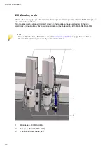
Page 209: ...Modules 209 8 Modules ...

Page 210: ...Modules 210 ...

Page 211: ...Material handling 211 9 Material handling ...

Page 212: ...Material handling 212 ...

Page 213: ...Additional specifications 213 10 Additional specifications ...

Page 214: ...Additional specifications 214 ...

Reviews: