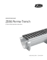
background image

L I N E A R   D R A I N AG E

Z886 Perma-Trench 

6" Perma-Trench Installation Instructions

Summary of Contents for Z886 Perma-Trench

Page 1: ...LI N E A R D R AI N AG E Z886 Perma Trench 6 Perma Trench Installation Instructions ...

Page 2: ...beginning your installation Contact customer service at 855 ONE ZURN should additional material be required P887 INLET 6 Inlet Adapter IA For Catch Basin Applications Shipping and Installation Bar GL Grate Lockdown Hardware P6 DGC 6 152 Double Iron Class C Grate P886 E4 NS 4 102 No Hub End Outlet P886 E1 NS Closed End Cap P886 U4 NS 4 102 No Hub Bottom Outlet Grate Lockdown Bar 840 Bag P886 JC NS ...

Page 3: ...MA TRENCH INSTALLATION INSTRUCTIONS Z886 Tools Required Tape Measure Phillips Head Screwdriver Hammer Utility Knife Marker Cordless Drill Reciprocating Saw Ear Protection Safety Glasses Gloves Hole Saw Caulk Gun ...

Page 4: ...te encasement and reinforcing based upon application and local codes Excavation Trench excavation must include the minimum of 4 102 on both sides and underneath or the slab thickness surrounding the trench Soft and or shifting soil substrates may cause cracking of the concrete and consequent movement of the trench It is critical that the concrete be poured on an adequate foundation Verify depth of...

Page 5: ...w direction indicating its sequence within the system It is best to work from the deep or outlet end to the shallow Grates are not installed at this time Four 4 shipping installation bars per channel recommended spacing is approximately 3 6 76 152 from end of rail for end pieces and 26 29 660 737 from end of rail for center pieces All shipping installation bar locations are approximate Female End ...

Page 6: ...own 2 Once overlap is removed trim end cap end outlet to desired height 3 Attach end outlet or end cap to the channel with hardware provided ATTACHING END CAPS AND OUTLETS Make sure all overlaps on trench are trimmed off prior to installing the end caps to ensure the finish installation has a frame above the trench channel This ensures each trench will have a grate on it Scrap Scrap Scrap ...

Page 7: ...Connection Option 1 Score both sides of the rib with the utility knife 2 Tap rib with a hammer to remove rib when necessary 4 Cut out hole with hole saw that matches inside diameter of outlet 3 Attach bottom outlet to channel with hardware provided Scrap Scrap Scrap ...

Page 8: ...ame on the ends that will be connected 1 Cut a 1 1 4 32 by 13 16 21 section out of the end of the channel This enables the end to act as a male end 2 Screw the ribs together with the hardware provided This method can also be used if you have a female to female connection 2 After removing the cutouts attach channel through the female connection with hardware provided 1 25 32 813 21 Scrap 1 25 32 81...

Page 9: ...with HD frame cut female ends to be flush with end of the HD frame on the ends that will be connected 2 Attach to the channels with the hardware provided 2 Screw the joint connector to the channel with the hardware provided This method can also be used if you have a male to male connection Ends are not cut off but ribs will need to be trimmed See page 7 Z886 Connecting the Trench Z886 HD Channel C...

Page 10: ...ill not intrude into the trench Silicone sealant may be used as a gasket between the channels for a better seal Channel connections may be welded with an HDPE welding gun for the best seal CONNECTIONS The maximum gap between frames is 1 4 6 Rebar length dictated by trench depth and substrate for positive anchoring while setting to resist floating 1 When using sidewalls with a joint connector be su...

Page 11: ...saw Cut out the material inside of the traced area including the upper lip under the frame Do not cut the frame 4 Slide the male end of the channel into the inlet adapter attaching them together with the supplied hardware and silicone caulk or construction adhesive 3 After the channel outline is removed from the catch basin cut the inlet adapter to the height of the hole in the basin Secure the in...

Page 12: ...his should be done for all sizes of basins Then remove the mechanical joint 2 Cutting the hole in the basin can be easily accomplished with the use of a hand saw or power reciprocating saw Cut out the material inside of the traced area 3 Slide the male end of the channel into the basin attaching them together with the supplied hardware and silicone caulk or construction adhesive through the ribbin...

Page 13: ...e of a hand saw or power reciprocating saw Cut out the material inside of the traced area 4 Slide the male end of the channel into the inlet adapter attaching them together with the supplied hardware and silicone caulk or construction adhesive 3 After the channel outline is removed from the catch basin cut the inlet adapter to just under the top of the mechanical joint Secure the inlet adapter to ...

Page 14: ... rebar stakes Slide the rebar into the rebar clips Then drive the stakes into the ground for positive anchoring Secure the trench to the rebar stakes with the hardware provided with bag No 841 Adjust the trench to the desired elevation and repeat the process with the next channel Set trench on rebar 1 25 above final grade this allows final elevation adjustment with a hammer prior to pouring concre...

Page 15: ... 1 8 shim or as required Z886 Setting the Trench BLOCKOUT RETROFIT HANGING An alternative means of installation is to suspend the trench drain as shown Wooden braces to hang the trench run can be attached to the drain body through the grate lockdown bars as illustrated below ...

Page 16: ...e layout drawings prior to pouring concrete Standard concrete practices with expansion and crack induction joints shall be followed based upon local codes and standards The trench drain shall not be used as an expansion joint Finish troweling should be done to set the top edge of the trench drain 1 8 3 below the floor grade Remember to compensate for the concrete shrink that may occur during cure ...

Page 17: ... Sidewall Extension Bracing INSTALLATION WITH SIDEWALL EXTENSIONS Use reinforcing every 10 254 per bracing schedule bracing provided by others Standard 2 x 4 s 51 x 102 Height Determined By Invert 10 254 TYP Height Determined by Invert Standard 2 x 4 s 51 x 102 ...

Page 18: ...reinforcing per bracing schedule bracing provided by others 4 Remove internal sidewall bracing 3 Using the standard concrete pouring method pour concrete so it is about 8 204 from the top of the trench 5 Pour the remaining concrete remove shipping installation bars and use standard finishing practices to finish the concrete POUR 1 POUR 2 6 25 159 4 102 MIN 4 102 8 203 ...

Page 19: ...addle the tie strap that spans the frame The exception is when both channels and frames are cut To place these grates line up the lockdown hole in the grate with the lockdown hole in the tie strap Lockdown bolts can be installed using a 1 2 13 socket LOCKING DOWN GRATES Start all lockdown bolts on each grate into the lockdown prior to tightening them down There may be gaps up to 1 4 6 to ensure al...

Page 20: ...Zurn Industries LLC 1801 Pittsburgh Avenue Erie PA 16502 855 663 9876 In Canada Zurn Industries Limited 37900 Goreway Drive Unit 10 Brampton Ontario L6T 5W6 905 405 8272 Form No ZMKTG220 11 Rev 11 16 ...

Reviews: