background image

Program Interface Library 

Windows, VxWorks, and Linux Programming 

CEI-100/CEI-200/CEI-

x20 User’s Manual


58 

CEI-x20 Programming 

The software distribution includes a robust Application Programming 
Interface (API) library for each CEI-x20 device.  The CEI-220, -420, and -
420A support the 

standard

 API, while the CEI-520, -520A, -620, -820, and 

-820TX support the 

enhanced

 API.  The enhanced API is a superset of the 

standard API.   

Under Windows, the standard API (CEI-220/420/420A) is provided as a 
32-bit DLL and both 32-bit and 64-bit DLLs are provided for the enhanced 
API (CEI-520/520A/620/820/820TX).  The 32-bit standard and enhanced 
API DLLs are named CEI22032.DLL, and the enhanced 64-bit API DLL 
is named CEI22064.DLL.  To interface with the API from a user 
application, link with one of the provided Microsoft-compatible or 
Borland-compatible LIB files.  Link 32-bit applications with 
CEI22032.LIB, and link 64-bit applications with CEI22064.LIB. 

The CEI-x20 Windows installer automatically determines the correct 32-
bit API DLL for the device type being installed and copies it into the 32-
bit Windows system folder.  If running under 64-bit Windows, the correct 
64-bit API DLL is copied into the 64-bit Windows system folder as well. 

To determine which 32-bit API DLL is in use under 32-bit or 64-bit 
Windows, use Windows Explorer to browse to the file CEI22032.DLL in 
the 32-bit Windows system folder (typically ‘c:\winnt\system32’ or 
‘c:\windows\system32’ under 32-bit Windows or ‘c:\windows\syswow64’ 
under 64-bit Windows).  Under the Version or Details tab, the 

File 

Description

 field lists the board types supported by the DLL.  The product 

list should include the board type you are trying to access.  Similarly, to 
determine which 64-bit API DLL is in use under 64-bit Windows, inspect 
the file CEI22064.DLL in the 64-bit Windows system folder (typically 
‘c:\windows\system32’ under 64-bit Windows). 

CEI-x20 products also support operation under Linux.  The Linux 
installation resides in a separate folder on the distribution CD, and Linux 
installation instructions can be found in the file, Linux_x20_install.txt, in 
the root directory on the distribution CD.  Under Linux, the installer places 
a shared library under the /usr/lib directory.  The library installed depends 
on the selected device type.  Installation of the CEI-220/420 places 
libcei22032.so under /usr/lib, installation of the CEI-520/620/820 places 
libceix2032.so under /usr/lib, and installation of the CEI-820TX places 
libcei820tx32.so under /usr/lib.  All Linux libraries are compiled with the 
GNU C compiler (gcc).   

Link your application to the shared library by including –lcei22032, –
lceix2032, or –lcei820tx32 in your Makefile or on the command line.  For 
example: 

Artisan Technology Group - Quality Instrumentation ... Guaranteed | (888) 88-SOURCE | www.artisantg.com

Summary of Contents for CEI-100 Series

Page 1: ...l service in house repair center WE BUY USED EQUIPMENT Sell your excess underutilized and idle used equipment We also offer credit for buy backs and trade ins www artisantg com WeBuyEquipment REMOTE INSPECTION Remotely inspect equipment before purchasing with our interactive website at www instraview com LOOKING FOR MORE INFORMATION Visit us on the web at www artisantg com for more information on ...

Page 2: ...User s Manual CEI 100 CEI 200 CEI x20 Artisan Technology Group Quality Instrumentation Guaranteed 888 88 SOURCE www artisantg com ...

Page 3: ...LITY ARISING FROM RELIANCE ON ANY INFORMATION CONTAINED HEREIN IS EXPRESSLY DISCLAIMED Microsoft is a registered trademark of Microsoft Corporation Windows is a registered trademark of Microsoft Corporation Abaco Systems Inc acknowledges the trademarks of other organizations for their respective products or services mentioned in this document CEI 100 CEI 200 CEI x20 User s Manual 1500 011 Document...

Page 4: ... CEI 820 Transition Cable Pin Out 11 Configuring the CEI 620 12 CEI 620 Outline Drawing 12 CEI 620 Input Output Connector Pin Out 12 CEI 620 Transition Cable Pin Out 15 Configuring the CEI 520 and CEI 520A 17 CEI 520 520A Outline Drawing 17 CEI 520 520A Input Output Connector Pin Out 17 CEI 520 520A Transition Cable Pin Out 21 Configuring the CEI 220 22 CEI 220 Outline Drawing 22 CEI 220 Base Memo...

Page 5: ...Out 34 CEI 100 CEI 200 Software Installation 35 CEI 100 CEI 200 Self test 35 CEI x20 Software Installation 36 CEI 220 420 420A 520 520A 620 820 820TX Self test 37 CEI 220 Discrete Inputs 37 CEI 420 420A 520 520A 620 820 Discrete Inputs 39 CEI 220 420 420A 520 520A 620 820 Discrete Outputs 40 Chapter 3 CEI 100 200 ARINC Test Program 42 General Information 42 Accessing the Program 43 Example 1 44 Ex...

Page 6: ...PI Information 65 Error Reporting 66 Tick Timer and Time Tag Functions 66 Channel Parameter Definition Setup 66 Channel Parameter Read Back 67 Mode Control 67 Channel Data Read Functions 67 Channel Data Write Functions 68 Label Filtering Functions 68 Data Structure Initialization Functions 68 Hardware Interrupt Control 68 Miscellaneous Functions 69 Board and Application Shutdown 69 AR _CANCEL_DATA...

Page 7: ...T_DUAL_PORT 105 AR_INIT_SLAVE 106 AR_INT_CONTROL 107 AR_INT_SET 109 AR_INT_SLAVE 110 AR_LABEL_FILTER 111 AR_LOADSLV 112 AR_MODIFY_MSG 114 AR_MSG_CONTROL 116 AR_NUM_RCHANS 118 AR_NUM_XCHANS 119 AR_PUTBLOCK 120 AR_PUTFILTER 121 AR_PUTWORD 122 ARINC 429 Transmit Data Format 122 ARINC 573 717 Transmit Data Format 122 CSDB Transmit Data Format 123 AR_PUTWORD2X16 125 AR_RECREATE_PARITY 126 AR_REFORMAT 1...

Page 8: ...ory Mapping 155 Building the CEI x20 API 156 Building the Sample Program 157 Chapter 7 Description of CEI 100 200 ARINC Interface 159 Overview 159 Loading the Board 160 Controlling the Board 160 Initializing the Board 160 Programming the ARINC Channel Setup 161 Controlling the Timers 162 Selecting the Receive Modes 162 Enabling Time Tags 162 Enabling Interrupts 163 Receiving Data 163 Filtering Out...

Page 9: ...DAC Definitions 175 CEI 520 520A DAC Definitions 175 CEI 620 DAC Definitions 176 CEI 820 DAC Definitions 176 Appendix D Example CEI x20 Programs 177 Introduction 177 NET Example Programs 177 Visual Basic 6 Example Program 177 LabWindows CVI Support 178 C C Example Programs 178 Artisan Technology Group Quality Instrumentation Guaranteed 888 88 SOURCE www artisantg com ...

Page 10: ... 11 CEI 220 P3 Connector Pinout 24 Figure 12 CEI 220 P4 Connector Pinout 25 Figure 13 CEI 420 420A Outline Drawing 25 Figure 14 CEI 420 420A P4 Front View 28 Figure 15 CEI 200 Outline Drawing 29 Figure 16 CEI 200 I O Connector Front View 31 Figure 17 CEI 100 Outline Drawing 32 Figure 18 CEI 100 I O Connector Front View 34 Figure 19 CEI 220 Discrete Inputs Circuit 37 Figure 20 CEI 420 420A 520 520A...

Page 11: ... Positions to Address Bits 22 Table 18 CEI 220 P3 Connector Change for ARINC 6 wire Configurations 24 Table 19 Mapping of Switch Positions to Address Bits 26 Table 20 CEI 420 420A P3 Front View 27 Table 21 CEI 420 420A P3 Pin Connections 28 Table 22 CEI 420 420A P4 Pin Connections 28 Table 23 CEI 200 Mapping of Switch Positions to Address Bits 29 Table 24 Default Address of 380 hex Example 30 Tabl...

Page 12: ...ge Lengths 123 Table 46 Supported Concurrency Modes 138 Table 47 Control Word Format 161 Table 48 Calculating a Clock Scaling Factor 167 Table 49 CEI 220 DAC Register Scale Factors 175 Table 50 CEI 520 520A DAC Register Scale Factors 175 Table 51 DAC Register Functions and Scaling Factors CEI 620 176 Table 52 DAC Register Functions and Scaling Factors CEI 820 176 Artisan Technology Group Quality I...

Page 13: ...20 can also support other protocols including CSDB ARINC 561 ARINC 568 and ARINC 573 717 Each of these boards has its own processor for interface control data formatting filtering and time tagging They have substantial dual port RAM for buffering of data The boards are powerful enough to support all of their channels running at maximum theoretical throughput simultaneously The hardware buffering m...

Page 14: ...6K or 32K 64K bytes 64K bytes 64K bytes 512K bytes 512K bytes 1M bytes 2M bytes Transmit Channels 1 Up to 4 Up to 12 Up to 8 Up to 8 Up to 16 Up to 16 Up to 8 Up to 32 Receive Channels 2 Up to 8 Up to 12 Up to 8 Up to 8 Up to 16 Up to 16 Up to 8 1 ARINC Transmit Bit Rates 12 5 or 100 Kbs 12 5 or 100 Kbs or programmable 12 5 or 100 Kbs 12 5 or 100 Kbs 12 5 or 100 Kbs 12 5 or 100 Kbs 12 5 or 100 Kbs...

Page 15: ...nd 5 amp max Up to 8 Open Ground 5 amp max share the same lines as discrete inputs 9 16 Up to 16 Open Ground 5 amp max Up to 16 Open Groun d 5 amp max Up to 16 Open Ground 5 amp max share the same lines as the discrete inputs None Variable ARINC receive threshold No No Yes software adjustable from 0 to 25 Vpp No No Yes Yes Yes No Variable ARINC transmit voltage No No Yes software adjustable from 0...

Page 16: ...ee workstation and be sure you are properly grounded Then remove the board from its static protective bag and inspect it Be aware of the potential for damage to this and any other circuit card by static electricity The board is shipped in a protective anti static bag and must be handled according to static prevention procedures Failure to protect the board from static electricity may result in dam...

Page 17: ...address space must not directly overlap with any other devices In addition you must avoid any indirect conflicts This occurs when a 16 bit memory interface such as the CEI 200 220 420 420A is placed in the same 128 Kbytes region i e segment address ranges A000 C000 or C000 E000 or E000 10000 as an 8 bit memory interface This is due to an inherent architectural limitation of the IBM PC Finally when...

Page 18: ...RINC 429 specification exactly for low speed slew rate you must install the appropriate jumpers Transmitting at low speed without the jumpers installed causes the ARINC waveform to be squarer than the specification defines However most ARINC 429 receivers can tolerate this Transmitting at high speed with the jumpers in place makes the waveform so far out of specification that it is not useable Con...

Page 19: ...26 47 TX24B 60 48 TX25A 27 49 TX25B 61 50 TX26A 28 51 TX26B 62 52 TX27A 29 53 TX27B 63 54 TX28A 30 55 TX28B 64 56 TX29A 31 57 TX29B 65 58 TX30A 32 59 TX30B 66 60 TX31A 33 61 TX31B 67 62 TX32A 34 63 TX32B 68 64 Signal pairs TXnA TXnB and RXnA RXnB are the positive and negative lines of an ARINC differential pair The ARINC receive channel is available only on the front bezel connector P1 Configurati...

Page 20: ...l connector P1 and a mezzanine PMC connector P14 are provided Figure 3 50 pin P1 connector AMP Champ 0 8 mm receptacle connectors AMP part number 787096 1 Table 3 CEI 820 xx and CEI 820 xxJ Connector Definitions P1 and P14 Signal P1 Pin P14 Pin Signal P1 Pin P14 Pin TX8A 1 9 TX8B 26 10 TX7A 2 11 TX7B 27 12 TX6A 3 13 TX6B 28 14 TX5A 4 15 TX5B 29 16 TX4A 5 17 TX4B 30 18 TX3A 6 19 TX3B 31 20 TX2A 7 2...

Page 21: ...t 16 64 P1 is a 50 pin Champ 0 8 mm receptacle connector The AMP part number is 787096 1 Signal pairs TXnA TXnB and RXnA RXnB are the positive and negative lines of an ARINC differential pair The discrete inputs and outputs share the same lines There are a total of 16 bi directional discretes on the CEI 820 each of which can be treated as an input or an output For example you may choose to use dis...

Page 22: ... 34 ARINC 429 RX3A 14 35 ARINC 429 RX3B 39 36 ARINC 429 RX2A 15 37 ARINC 429 RX2B 40 38 ARINC 429 RX1A 16 39 ARINC 429 RX1B 41 40 GND 17 19 23 41 47 GND 42 44 48 42 48 Discrete Input Output 1 20 49 Discrete Input Output 2 45 50 Discrete Input Output 3 21 51 Discrete Input Output 4 46 52 Discrete Input Output 5 24 53 Discrete Input Output 6 49 54 Discrete Input Output 7 25 55 Discrete Input Output ...

Page 23: ...Signal P1 D50 Signal 25 17 Discrete Input Output 7 50 50 Discrete Input Output 8 24 49 Discrete Input Output 5 49 33 Discrete Input Output 6 23 32 GND 48 16 GND 21 47 Discrete Input Output 3 46 31 Discrete Input Output 4 20 30 Discrete Input Output 1 45 14 Discrete Input Output 2 19 13 GND 44 46 GND 17 28 GND 42 12 GND 16 11 RX1A 41 44 RX1B 15 43 RX2A 40 27 RX2B 14 26 RX3A 39 10 RX3B 13 9 RX4A 38 ...

Page 24: ... Input Output Connector Definition Row a Row b Row c Row d Row e 22 Discrete Output 16 Discrete Output 12 Discrete Output 9 Discrete Output 6 Discrete Output 3 21 Discrete Output 15 Discrete Output 11 Discrete Output 8 Discrete Output 5 Discrete Output 2 20 Discrete Output 14 Discrete Output 10 Discrete Output 7 Discrete Output 4 Discrete Output 1 19 Discrete Output 13 Discrete Input 12 Discrete I...

Page 25: ... to the edge of the circuit board and Row E is furthest from the edge of the circuit board Signal pairs TXnA TXnB and RXnA RXnB are the positive and negative lines of an ARINC differential pair Optional non ARINC 429 protocols are assigned to the following channels for configurations that support them Protocol Receive channel s Transmit channel s ARINC 573 717 Bipolar return to zero encoding 1 1 T...

Page 26: ...ut 1 43 Discrete Input 2 18 Discrete Input 9 43 Discrete Input 10 17 GND 42 GND 17 GND 42 GND 16 RX8A 41 RX8B 16 RX16A 41 RX16B 15 RX7A 40 RX7B 15 RX15A 40 RX15B 14 RX6A 39 RX6B 14 RX14A 39 RX14B 13 RX5A 38 RX5B 13 RX13A 38 RX13B 12 RX4A 37 RX4B 12 RX12A 37 RX12B 11 RX3A 36 RX3B 11 RX11A 36 RX11B 10 RX2A 35 RX2B 10 RX10A 35 RX10B 9 RX1A 34 RX1B 9 RX9A 34 RX9B 8 TX8A 33 TX8B 8 TX16A 33 TX16B 7 TX7A...

Page 27: ...Out Table 10 defines the CONCEI 620 cable provided with each CEI 620 The cable is approximately three feet in length There is a Champ 0 8mm 50 pin connector AMP 787131 1 on one end The other end is a standard subminiature D 50 pin plug connector AMP p n 205212 3 or equivalent Table 10 CEI 620 Transition Cable Pin Out P1 Connector P2 Connector P1 D50 Signal P2 D50 Signal 25 17 Discrete Output 7 25 ...

Page 28: ...te Output 16 49 33 Discrete Output 6 49 33 Discrete Output 14 48 16 Discrete Output 4 48 16 Discrete Output 12 47 48 Discrete Output 2 47 48 Discrete Output 10 46 31 Discrete Input 8 46 31 Discrete Input 16 45 14 Discrete Input 6 45 14 Discrete Input 14 44 46 Discrete Input 4 44 46 Discrete Input 12 43 29 Discrete Input 2 43 29 Discrete Input 10 42 12 GND 42 12 GND 41 44 RX8B 41 44 RX16B 40 27 RX7...

Page 29: ...provides configuration information for the CEI 520 and the CEI 520A CEI 520 520A Outline Drawing Figure 6 CEI 520 520A Outline Drawing CEI 520 520A Input Output Connector Pin Out To couple the CEI 520 520A to ARINC devices using the rear panel the following rear panel connector is provided AMP Tyco 787171 1 Figure 7 68 pin Receptacle Connector SCSI 3 compatible with rails and latch blocks view fac...

Page 30: ... 51 GND 34 RX16 68 RX16 For external wrap connect each transmit signal to the corresponding receive signal e g TX1 to RX1 TX1 to RX1 etc Also available are the CEI 520 1208 C CEI 520A 1208 C which provide CSDB support and the CEI 520 xxxx J CEI 520A xxxx J which provide ARINC 573 717 support The P2 connector pinouts for these configurations are shown in the following tables Table 12 Front View CEI...

Page 31: ...3 4 TX4 38 TX4 21 RX4 55 RX4 5 TX5 39 TX5 22 RX5 56 RX5 6 TX6 40 TX6 23 RX6 57 RX6 7 TX7 41 TX7 24 RX7 58 RX7 8 TX8 42 TX8 25 RX8 59 RX8 9 TX9 43 TX9 26 GND 60 GND 10 TX10 44 TX10 27 RX9 61 RX9 11 TX11 45 TX11 28 RX10 62 RX10 12 TX12 46 TX12 29 RX11 63 RX11 13 TX13 47 TX13 30 RX12 64 RX12 14 TX14 48 TX14 31 RX13 65 RX13 15 TX15 49 TX15 32 RX14 66 RX14 16 TX16 50 TX16 33 RX15 67 RX15 17 GND 51 GND ...

Page 32: ...ormation for the discrete I O connector 2 4 6 8 10 12 14 16 18 20 22 24 26 28 30 32 34 36 38 40 42 44 46 48 50 1 3 5 7 9 11 13 15 17 19 21 23 25 27 29 31 33 35 37 39 41 43 45 47 49 Figure 8 50 pin IDC style Discrete I O connector 3M Part Number 2550 6002 UB Table 15 Top View Discrete Input Output Connector P3 Pin Signal Pin Signal 1 Discrete Input 1 2 Discrete Input 2 3 Discrete Input 3 4 Discrete...

Page 33: ...out to a 37 pin D sub female connector mounted on a PC expansion card end panel is available For details search our web site for the part number CONM50 D37 A 30 version of the adapter cable is also available CONM50 D37 30 A mating connector for P3 on the CEI 520 520A is shown in Table 16 Table 16 CEI 520 520A P3 Mating Connector Manufacturer 3M Connector 925110 50 R CEI 520 520A Transition Cable P...

Page 34: ...ress bits and uses the default address of D000 hex as an example The CEI 220 takes up 4Kb i e 1000 Hex of upper memory block memory space Table 17 Mapping of Switch Positions to Address Bits Jumper Position A19 A18 A17 A16 A15 A14 A13 A12 Address Bit 19 18 17 16 15 14 13 12 Jumper Setting Off Off On Off On On On On Base address 1 1 0 1 0 0 0 0 Hex value D 0 Other sample settings for jumpers A19 th...

Page 35: ...listed in Figure 11 The end panel connector P3 is female and the rear connector P4 is male To make an external wrap adapter use a DB37 male connector and tie pin 1 to 20 2 to 21 etc through 18 to 37 Pin Signal Pin Signal P3 1 TX1 P3 20 RX1 P3 2 TX1 P3 21 RX1 P3 3 TX2 P3 22 RX2 P3 4 TX2 P3 23 RX2 P3 5 TX3 P3 24 RX3 P3 6 TX3 P3 25 RX3 P3 7 TX4 P3 26 RX4 P3 8 TX4 P3 27 RX4 P3 9 TX5 Note 1 P3 28 RX5 N...

Page 36: ...ions Pin Signal P3 9 ARINC 561 transmit data P3 19 ARINC 561 transmit data ground P3 11 ARINC 561 transmit clock P3 19 ARINC 561 transmit clock ground P3 13 ARINC 561 transmit sync P3 19 ARINC 561 transmit sync ground P3 28 ARINC 561 receive data P3 29 ARINC 561 receive data P3 30 ARINC 561 receive clock P3 31 ARINC 561 receive clock P3 32 ARINC 561 receive sync P3 33 ARINC 561 receive sync Pin Fu...

Page 37: ...4 31 DISINLO3 P4 13 DISOUT1 P4 32 DISINHI4 P4 14 GND P4 33 DISINLO4 P4 15 P4 34 P4 16 P4 35 P4 17 P4 36 P4 18 P4 37 P4 19 Factory use only Connecting these pins may damage the board Figure 12 CEI 220 P4 Connector Pinout Configuring the CEI 420 and CEI 420A This section provides configuration information for the CEI 420 420A CEI 420 420A Outline Drawing Figure 13 CEI 420 420A Outline Drawing Artisa...

Page 38: ...ting Off Off On Off On On On On Base Address 1 1 0 1 0 0 0 0 Hex Value D 0 Other sample settings for jumpers A19 through A12 respectively generate the following base memory addresses D800 Off Off On Off Off On On On E000 Off Off Off On On On On On CEI 420 420A Interrupts and Slew Rate The interrupts are software controlled See chapter 5 Program Interface Library for information on selecting interr...

Page 39: ...25 23 21 19 17 15 13 11 9 7 5 3 1 40 38 36 34 32 30 28 26 24 22 20 18 16 14 12 10 8 6 4 2 Board Edge Pin Signal Pin Signal 1 TX1 2 TX1 3 TX2 4 TX2 5 TX3 6 TX3 7 TX4 8 TX4 9 TX5 10 TX5 11 TX6 12 TX6 13 TX7 14 TX7 15 TX8 16 TX8 17 RX1 18 RX1 19 RX2 20 RX2 21 RX3 22 RX3 23 RX4 24 RX4 25 GND 26 GND 27 RX5 28 RX5 29 RX6 30 RX6 31 RX7 32 RX7 33 RX8 34 RX8 35 GND 36 GND 37 38 39 40 For external wrap conn...

Page 40: ...t View Table 22 CEI 420 420A P4 Pin Connections CEI 420A CEI 420 PIN SIGNAL PIN SIGNAL PIN SIGNAL PIN SIGNAL 1 DISOUT1 DISIN9 2 DISOUT2 DISIN10 1 DISOUT1 2 DISOUT2 3 DISOUT3 DISIN11 4 DISOUT4 DISIN12 3 DISOUT3 4 DISOUT4 5 DISOUT5 DISIN13 6 DISOUT6 DISIN14 5 DISOUT5 6 DISOUT6 7 DISOUT7 DISIN15 8 DISOUT8 DISIN16 7 DISOUT7 8 DISOUT8 9 GND 10 GND 9 GND 10 GND 11 DISIN1 12 DISIN2 11 DISIN1 12 DISIN2 13...

Page 41: ...rt The following table demonstrates mapping of switch positions to address bits It uses the default address of D000 hex as an example The CEI 200 takes up 32Kb of memory space Table 23 CEI 200 Mapping of Switch Positions to Address Bits Switch Position 1 2 3 4 5 6 7 Address Bit 21 20 19 18 17 16 15 14 13 12 Switch Setting On On Off Off On Off On Base address 0 0 1 1 0 1 0 0 0 0 Hex value 0 D 0 Oth...

Page 42: ...ses 388 Off On On On Off 390 Off On On Off On CEI 200 Interrupts and Slew Rate Jumper blocks J2 and J3 located in the upper right corner of the board are used to set the ARINC transmit data slew rates With no jumpers in place slew rates are set for the high 100Kbs bit rate To set up a channel for low speed transmission attach two jumpers for each channel For example to set up channel 2 for low spe...

Page 43: ...re listed in Figure 16 and Table 27 To build a loop back connector for the external wrap around test connect the following three pin groups 1 2 3 4 5 6 7 8 9 10 11 12 14 15 16 17 18 19 20 21 22 and 23 24 25 This connects receivers 1 and 2 to transmitter 1 receivers 3 and 4 to transmitter 2 etc 13 25 14 1 Figure 16 CEI 200 I O Connector Front View Table 27 CEI 200 I O Connector Pin Assignments Pin ...

Page 44: ... through 6 on the dipswitch at U26 set the CEI 100 base address The following example demonstrates the default address of CC00 Table 28 Default Address of CC00 Example Switch Position 1 2 3 4 5 6 Address Bit 19 18 17 16 15 14 13 12 Switch Setting Off On On Off Off On Base address 1 1 0 0 1 1 0 0 Hex value C C Other sample settings for switches 1 through 6 respectively generate the following base s...

Page 45: ...n the lower right corner of the board sets the host interrupt level and the ARINC transmit data slew rate With no jumpers in place there is no host interrupt enabled and the slew rate is set for the high 100Kbs bit rate To enable an interrupt select one of the three interrupt levels IRQ3 IRQ4 or IRQ5 and install its jumper For example a jumper between locations 1 and 2 enables interrupts on IRQ3 I...

Page 46: ...ns 1 3 and 5 and pins 2 4 and 6 This connects the output of the transmitter to the input of the two receivers The test pins are for discrete inputs which are not currently supported in the firmware Figure 18 CEI 100 I O Connector Front View Table 31 CEI 100 I O Connector Pin Assignments Pin Function 1 Transmitter 1 A 2 Transmitter 1 B 3 Receiver 1 A 4 Receiver 1 B 5 Receiver 2 A 6 Receiver 2 B 7 T...

Page 47: ...ibed in chapter 3 CEI 100 200 ARINC Test Program To quickly verify that the board is connected properly start the program CONDOR EXE from DOS by typing if configured at the default addresses CONDOR If the board is using different addresses include the addresses in the command For example for I O address 388 memory address E000 type CONDOR M E000 I 388 If the program says 1 CEI 100 CEI 200 ARINC co...

Page 48: ...LL To interface with the API from a user application link with one of the provided Microsoft compatible or Borland compatible LIB files Link 32 bit applications with CEI22032 LIB and link 64 bit applications with CEI22064 LIB The CEI x20 Windows installer automatically determines the correct 32 bit API DLL for the device type being installed and copies it into the 32 bit Windows system folder If r...

Page 49: ... Inputs Each of the CEI 220 discrete inputs has a circuit as shown in Figure 19 470K 47K 47K 0 01uF DISINHIn DISINLOn Logic level Output GND Programmable Comparator Threshold 0 to 5V Comparator JUMPER J2 Discrete input 1 J3 Discrete input 2 J4 Discrete input 3 J5 Discrete input 4 Figure 19 CEI 220 Discrete Inputs Circuit The CEI 220 has four single ended unipolar discrete inputs which can be confi...

Page 50: ...supply voltage Avionics High Low Input is driven between a supply voltage and 0 Volts CMOS TTL Input is driven by either a TTL or CMOS 5V or 3 3V driver CMOS TTL Open Collector Either an open collector or open drain logic device drives input The CEI 220 provides a 47K pull up resistor to the voltage applied to the DISINHIn input The maximum threshold is 4 98 Volts Table 33 CEI 220 Discrete Input O...

Page 51: ... Table 35 Read Discrete Input AR_GET_CONFIG Format Discrete 3 2 1 0 Value condition 0 VIN 3 VTH 1 VIN 3 VTH 0 VIN 2 VTH 1 VIN 2 VTH 0 VIN 1 VTH 1 VIN 1 VTH 0 VIN 0 VTH 1 VIN 0 VTH 1 There is 4mV jumper not installed of internal hysteresis for clean switching 2 VTH Threshold Voltage 3 VIN 0 Discrete 0 Input Voltage CEI 420 420A 520 520A 620 820 Discrete Inputs Each of the CEI 420 420A 520 520A 620 ...

Page 52: ...ations CEI 420 520 520A 620 820 Discrete Input Specifications Input voltage range 20 volts to 100 volts continuous Input threshold Approximately 3 3 V Because of the 4 7K pull up resistor the discrete will switch high as long as the discrete input source does not source current near the threshold voltage This allows for compatibility with TTL type signals CEI 220 420 420A 520 520A 620 820 Discrete...

Page 53: ...e suitable for driving resistive loads solenoids relays lamps and other loads not exceeding the specifications in Table 37 See the previous section CEI 420 420A 520 520A 620 820 Discrete Inputs for additional information regarding the CEI 820 discretes Table 37 Discrete Output Specifications Maximum Drain to source Volts Maximum On Resistance at 1A Ohms Diode Forward Voltage Drop Volts Continuous ...

Page 54: ... units multiple buffering mechanisms and powerful triggering logic Strings of outgoing messages can be generated repeated or automatically stepped though a sequence Strings of incoming messages can be filtered and captured for current or future analysis A database is provided of the standard BCD and BNR message formats of both the ARINC 429 11 and ARINC 429 12 Specifications for the Mark 33 Digita...

Page 55: ...u can use the following command line switches to when calling the program They can be used in any order The default I O address is 380 hex The default segment is CC00 for the CEI 100 and D000 hex for the CEI 200 This program automatically configures for the board type found at the selected I O address All command line switches and arguments must be separated by at least one space M XXXX Indicates ...

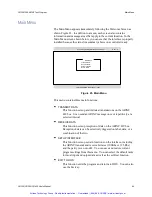
Page 56: ...mple 2 CONDOR C AVIATOR CFG In this example the program starts running using the previously saved configuration in file AVIATOR CFG This information includes the segment address I O address and RAM size of the board Previously saved configuration data can also be entered after starting the program The Setup menu provides this capability as does the hot key Alt R Hot Keys The following keys are sho...

Page 57: ...ons TRANSMIT DATA This function sets up and initiates transmissions on the ARINC 429 bus It can send an ARINC message once or repetitively at a selected interval RECEIVE DATA This function sets up reception of data on the ARINC 429 bus Reception of data can be selectively triggered on label data or a combination of the two SETUP INTERFACE This function sets up certain functions on the interface in...

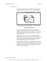
Page 58: ...re used to set up the interface INITIALIZE TEST BOARD This is a sub function to initialize parameters on the installed board See Board Setup for details SELECT DEFAULT RADIX Selects the default radix for most input and output Valid choices are HEX or OCTAL SAVE CONFIGURATION Saves the current configuration which includes all transmit message data information receive setup configuration and all boa...

Page 59: ... odd and even The board shown in Figure 25 is set to operate at transmit and receive bit rates of 100K using odd parity This menu also allows you to run the self tests described in chapter 2 Installation Execute self test runs a wrap around test The board can be tested through an external or an internal loop The external test uses a wrap around connector between the transmit and receive channels T...

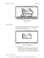
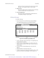
Page 60: ...ansmit Menu The Transmit Menu is used to define a message to be transmitted to select between single or repeated transmission and to start the transmission process The menu is shown in Figure 27 Repeat Mode Stopped Radix HEX Condor Engineering ARINC 429 Controller Rev 1 0 Main Menu Define message Repeat Step Start transmitting Return to main menu Transmit Menu Figure 27 Transmit Menu DEFINE MESSAG...

Page 61: ...29 Controller Rev 1 0 Transmit Message Definition Form 1 6 002200 002300 002400 002500 002600 002700 7 12 002800 002900 003000 003100 003200 003300 13 18 003400 003500 003600 003700 003800 003900 19 24 004000 004100 004200 004300 004400 004500 25 30 004600 004700 004800 31 36 37 42 43 48 49 54 55 60 Transmit Message Data Figure 28 Transmit Message Definition Form 2 Select a valid transmit channel ...

Page 62: ...29 Controller Rev 1 0 Main Menu Define message Repeat Step Start transmitting Return to main menu Transmit Menu Transmission initiated Enter any key to terminate Messages Figure 29 Screen during Transmission ReceiveMenu The receive function allows you to read ARINC data on any channel at the selected bit rate with any requested trigger The data is stored in a circular buffer for subsequent viewing...

Page 63: ...les the current receive channel through the available receive channels SETUP TRIGGERING Triggers on an ARINC data condition that is of interest One trigger condition is provided The trigger condition can be used to start or stop buffering See Triggering for details TOGGLE DISPLAY FORMAT Toggles a data display between Normal format which includes display fields for label and data and ARINC format w...

Page 64: ...efine Trigger Bits Figure 31 Trigger Bit Definition Triggering Logic As each data word is received it is checked against the trigger condition If the word meets the condition the trigger status is considered TRUE and a trigger has occurred The trigger condition is met if for each trigger bit specified as a 1 the corresponding bit in the data word is a 1 and for each trigger bit specified as a 0 th...

Page 65: ... are detected in a message or the messages are stored after the trigger bits are detected You can then examine the buffer and store it to a file from the Receive Menu The optional program ANALYZER EXE provides sophisticated forms of triggering filtering and data capture ANALYZER EXE also provides expanded capability for data translation and analysis Artisan Technology Group Quality Instrumentation...

Page 66: ... streams data to disk or memory and replays it in a time sequenced display It provides multiple buffering mechanisms including real time display of data in engineering units Strings of outgoing messages are generated repeated or automatically stepped through a sequence Strings of incoming messages are filtered and captured for current or future analysis A database of standard ARINC 429 translation...

Page 67: ...EI 200 and all CEI x20 boards When data is received from an input channel the interface places it in that channel s buffer On the CEI 100 board all three buffers two receive and one transmit are 512 ARINC words in size On the DTI 1073 4 all three buffers are 128 ARINC words in size Table 38 shows the transmitter and receiver buffer sizes for the various configurations of the CEI 200 Table 38 CEI 2...

Page 68: ...Buffer Size 512 words 512 words 4096 words 4096 words 4096 words n a Scheduled Mode Buffer 120 Labels 120 Labels 120 Labels 120 Labels 120 Labels 120 Labels Concurrent Burst and Scheduled Transmit No No Yes Yes Yes Yes Dedicated Mode Buffer Shared with Rx Shared with Rx Separate buffer Separate buffer Separate buffer Separate buffer Concurrent Buffered Dedicated Receive No No Yes Yes Yes Yes 573 7...

Page 69: ...f the CEI x20 distribution which contain DOS support for the CEI 220 and CEI 420 CEI 420A are available Contact the factory for more information Windows VxWorks and Linux Programming First verify that the operating system you are planning to use is supported by your particular board type To determine which operating systems are supported by each board type refer to the file README HTML This file c...

Page 70: ...ows use Windows Explorer to browse to the file CEI22032 DLL in the 32 bit Windows system folder typically c winnt system32 or c windows system32 under 32 bit Windows or c windows syswow64 under 64 bit Windows Under the Version or Details tab the File Description field lists the board types supported by the DLL The product list should include the board type you are trying to access Similarly to det...

Page 71: ...rocessing ARINC data Subsequently the host program could again call AR_GO to restart the interface AR_INIT_SLAVE may be invoked first to reset the slave queue pointers which flush out any remaining data in the queues Unlike the CEI 100 200 boards all of the boards in the CEI x20 family support independent programming of each channel s parameters Further each channel may be reprogrammed at any time...

Page 72: ... order bit 8 first bit 1 last The CEI 100 200 x20 hardware works with labels that are formatted in the normal bit order During transmission it automatically shifts the bits out on the bus in the correct inverted order During reception it formats and returns the bits in the proper order as well There is no need for you to invert the label before or after transmission Transmission Order ARINC conven...

Page 73: ...verridden using the routine AR_SET_RAW_MODE which can be used to disable parity altogether CEI x20 Interrupt Support Functions are included in the CEI x20 API to allow configuration of hardware interrupt generation The current API does not provide a user application interrupt handler function If your application uses hardware interrupts you have to supply an interrupt handler as needed by your ope...

Page 74: ... AR_GETWORD or AR_GETWORDT waiting to receive a word on the channel in question then disabling await data mode on that channel also cancels the pending wait Note that await data mode cannot be enabled unless internal interrupt handling has also been enabled Refer to AR_SET_PRELOAD_CONFIG documentation for a discussion of internal interrupt handling limitations Utility Routines Summary This section...

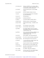
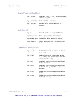
Page 75: ...ode Get raw mode no parity status ar_get_rx_count Returns count of received data words for a channel ar_get_timercnt Gets the number of timer ticks that have occurred on interface 16 bits ar_get_timercntl Gets the number of timer ticks that have occurred on interface 32 bits ar_getblock Gets multiple ARINC words from a channels receiver buffer CEI 520 520A 620 820 820TX enhanced interface only ar_...

Page 76: ...umber of transmit channels ar_putblock Puts multiple ARINC words into a channels transmit buffer CEI 520 520A 620 820 820TX enhanced interface only ar_putfilter Sets the entire filter buffer for an ARINC receiver channel CEI 520 520A 620 820 820TX enhanced interface only ar_putword Puts an ARINC word in the transmit buffer ar_putword2x16 Put 2 16 bit words into the burst transmit queue ar_recreate...

Page 77: ...xecution of the calling thread CEI x20 API only ar_timetag_control Enables or disables time tags on received ARINC data ar_version Gets the API software and board firmware versions as an ASCII string ar_xmit_sync Waits for the transmit queue to be empty Utility Routines By Function This section lists all of the utility routines in the API by function Board and API Initialization ar_loadslv Loads a...

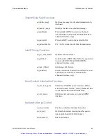
Page 78: ...s the resolution of the slave receive timer ar_timetag_control Enables or disables time tags on received ARINC data Channel Parameter Definition Setup ar_clr_rx_count Zeros out count of received data words ar_define_msg Defines a message for scheduling by the ARINC board ar_set_config Sets ARINC channel configuration information ar_set_preload_config Update a pre load configuration setting CEI 520...

Page 79: ...e ar_msg_control Selects transmission logic scheduled or burst mode Channel Data Read Functions ar_get_latest Gets the latest data from a particular dedicated mode label ar_getblock Gets multiple ARINC words from a channels receiver buffer CEI 520 520A 620 820 820TX enhanced interface only ar_getnext Gets the next ARINC word from the sequential buffer Wait if none ar_getnextt Gets the next ARINC w...

Page 80: ...fer for a specified receiver CEI 520 520A 620 820 820TX enhanced interface only ar_label_filter Initializes label filter s ar_putfilter Sets the entire filter buffer for an ARINC receiver channel CEI 520 520A 620 820 820TX enhanced interface only Data Structure Initialization Functions ar_init_dual_port Initializes all ARINC queue structures buffers and word counts Calls ar_reset flushes all data ...

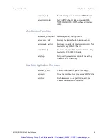
Page 81: ...tion ar_recreate_parity Recreate the parity bit for a received word Not needed for any CEI x20 board ar_reformat Converts output word to transmit format Only needed for CEI 100 200 boards ar_sleep Temporarily suspend execution of the calling thread CEI x20 API only Board and Application Shutdown ar_xmit_sync Waits for the transmit queue to be empty ar_reset Stops the interface from processing ARIN...

Page 82: ...GETWORD or AR_GETWORDT returns ARS_NODATA A call to AR_CANCEL_DATA_WAIT may return before the waiting thread if any has fully processed the cancellation request Use AR_SET_CONFIG to disable await data mode on a particular receiver Note that AR_CANCEL_DATA_WAIT does not disable await data mode on the channel in question ARS_NORMAL Operation completed successfully ARS_INVBOARD Invalid board number A...

Page 83: ...s mode is active this routine does not shut down the board if it is still opened by another process Refer to AR_SET_PRELOAD_CONFIG documentation for details ARS_NORMAL Operation completed successfully ARS_INVBOARD Invalid board number ARS_BOARD_MUTEX Failed to acquire release the board lock ARS_CONFIG_MUTEX Failed to acquire release the board configuration lock ARS_THREAD_WAITING An await data mod...

Page 84: ...o zero The firmware maintains a count of ARINC data words received over the interface for each channel since the interface was initialized or since the count was reset To read the current value of the count see the routine AR_GET_RX_COUNT None board input board number channel input receive channel number Syntax Description Return Value Arguments Artisan Technology Group Quality Instrumentation Gua...

Page 85: ...of all messages call the function AR_INIT_DUAL_PORT That function operates on all channels so it will clear all message buffer settings If you have a CEI 520 520A 620 820 820TX the enhanced API supports SIGNALED MESSAGES In this mode a specified ARINC receiver looks for a specified label The filter can be setup to look for any combination of filtered bits as follows eSSM SDI label Bits 30 29 28 9 ...

Page 86: ...number assigned to this message Each channel assigns message numbers in this range board input board number of interest channel input transmit channel of interest rate input re transmission rate of the message in clock ticks start input initial delay in ticks from the current time until the message is transmitted for the first time Subsequent transmissions of this data are at the rate defined in t...

Page 87: ...ests for details Supported Built In Tests AR_BIT_BASIC_STARTUP Performs all startup testing executed by the AR_LOADSLV routine dual port memory the on board processor and the on board FPGA are tested The board is reinitialized during this test AR_BIT_PERIODIC Verifies that the board is running by confirming that the on board tick timer is being properly incremented The board must be launched by ca...

Page 88: ...cess mode if supported and more than one process has loaded the board Refer to the documentation of AR_SET_PRELOAD_CONFIG for a discussion of multi process limitations All loopback testing operations support balanced ARINC 429 channels only as described above All ARINC 573 717 ARINC 561 and CSDB channels are excluded from loopback testing To test an ARINC 573 717 channel refer to the sample applic...

Page 89: ...on for all CEI x20 boards If boardName is not a NULL pointer the resulting ASCII string is copied to the buffer that boardName points to which should be at least 120 characters long The function returns a pointer to the NULL terminated ASCII string describing the board Pointer to a string describing the specified board board input the board number boardName output address to receive the board desc...

Page 90: ...ected HW CEI_220 4 CEI 220 board is selected HW CEI_420 5 CEI 420 board is selected HW CEI_520 6 CEI 520 board is selected HW CEI_620 10 CEI 620 board is selected HW CEI_820 11 CEI 820 board is selected HW CEI_420A 13 CEI 420A board is selected HW CEI_420A_12 14 CEI 420A 12 MHz board is selected HW CEI_420_70J 15 CEI 420 70J 12 MHz reduced comp HW CEI_820TX 17 CEI 820TX board is selected HW CEI_52...

Page 91: ... board lock ARS_BOARD_MUTEX is returned If the requested item is ARU_Xn_RATE or ARU_Rn_RATE where n is the transmitter number or receiver pair number CEI 100 200 only then this routine returns AR_HIGH high rate 100Kbs AR_LOW low rate 12 5Kbs If the requested item is ARU_RnXm_PARITY where n is the receiver pair number and m is the transmitter number CEI 100 200 only this routine returns AR_ODD odd ...

Page 92: ...K baud receiver rate selected If the requested CEI x20 item is ARU_TX_CHnn_BIT_ RATE where nn is the transmitter channel 01 32 this function returns AR_HIGH 100 Kbaud receiver rate selected AR_LOW 12 5 Kbaud receiver rate selected If the requested CEI x20 item is ARU_RX_CHnn_PARITY where nn is the receiver channel 01 32 this function returns AR_ODD odd receiver parity AR_OFF receiver parity off If...

Page 93: ..._GAP_INJ where nn is the transmitter channel 01 32 this function returns AR_ON Transmit short gap is enabled AR_OFF Transmit short gap disabled normal operation If the requested CEI x20 item is ARU_RX_CHnn_WAIT_PENDING where nn is the receiver channel 01 32 this function returns AR_TRUE There is currently a pending await data mode wait operation on this receiver AR_FALSE There is currently no pend...

Page 94: ...ARU_DAC_VALUE_01 ARU_DAC_VALUE_16 See appendix C Parametric Voltage Programming to determine the DAC register definitions for your board The following items allow you to enable disable variable transmitter voltage levels on the CEI 520 520A 620 on a per channel basis ARU_OUTPUT_LEVEL_ADJ_01 ARU_OUTPUT_LEVEL_ADJ_32 If the requested CEI 220 520 520A 620 820 820TX item is ARU_PARAMETERIC_SUPPORT this...

Page 95: ...eiver 6 SDI prefilter enable ARU_R7_SDI_FILTER receiver 7 SDI prefilter enable ARU_R8_SDI_FILTER receiver 8 SDI prefilter enable ARU_R1_SDI_VALUE receiver 1 SDI prefilter value ARU_R2_SDI_VALUE receiver 2 SDI prefilter value ARU_R3_SDI_VALUE receiver 3 SDI prefilter value ARU_R4_SDI_VALUE receiver 4 SDI prefilter value ARU_R5_SDI_VALUE receiver 5 SDI prefilter value ARU_R6_SDI_VALUE receiver 6 SDI...

Page 96: ...arametrics supported or not ARU_DISCRETE_INPUTS current value of discrete inputs ARU_TX_CH01_HB_INJ ARU_TX_CH32_HB_INJ high bit injection on off ARU_TX_CH01_LB_INJ ARU_TX_CH32_LB_INJ low bit injection on off ARU_TX_CH01_GAP_INJ transmit short gap ARU_TX_CH32_GAP_INJ enabled disabled CEI 520 520A 620 820 only values ARU_RX_CH01_AWAIT_DATA is await data mode currently ARU_RX_CH32_AWAIT_DATA enabled ...

Page 97: ...mation if any is available There is only one extended error buffer per process so you should retrieve this information immediately after an error has occurred to prevent its contents from being over written Not all errors generate extended error information If no extended error information is available ARS_LAST_ERROR returns the extended error information from the previous error that generated ext...

Page 98: ...LABEL_FILTER or for the CEI 520 520A 620 820 820TX enhanced API the function AR_PUTFILTER The value of the label filter for all channels is returned by this function This value consists of a bit field the least significant bit is set if the label is filtered out on channel 0 the next bit is set if the label is filtered out on channel 1 etc board input the board of interest label input the label of...

Page 99: ...urns a data word containing all zeros if no labels have been received If you are using the CEI 520 520A 620 820 820TX enhanced API the DEDICATED storage mode is always operational and this function is enhanced as follows The entry point AR_GET_LATEST is used to return the latest value for a label channel This function gets data from the DEDICATED storage mode Snap Shot buffer SnapRBuf It returns t...

Page 100: ...nel number label input label number data output address of the location to receive the 32 bit ARINC word s The returned ARINC data is in normal ARINC format seqno output address of the location to receive the 8 bit sequence number s Arguments Artisan Technology Group Quality Instrumentation Guaranteed 888 88 SOURCE www artisantg com ...

Page 101: ...ion is used to inquire about the parity enable status of a channel AR_ON if raw mode is on parity is disabled AR_OFF if raw mode is off parity is enabled board input board number direction input channel type ARU_XMIT or ARU_RECV channel input channel number Syntax Description Return Value Arguments Artisan Technology Group Quality Instrumentation Guaranteed 888 88 SOURCE www artisantg com ...

Page 102: ...l since the interface was initialized or since the count was reset see AR _CLOSE This routine returns that number On the CEI 100 only the returned value is 32 bits but the data has only 16 bit accuracy The most significant 16 bits are not used Count of ARINC data words board input board number channel input receive channel number Syntax Description Note Return Value Arguments Artisan Technology Gr...

Page 103: ...alized see AR_LOADSLV or since the counter was reset to zero see AR_RESET_TIMERCNT This value determines if a specific time interval has passed to help in the timed re transmission of ARINC data The resolution of a tick is programmable through the routine AR_SET_TIMERRATE The number of timer ticks 16 bits wide board input board number from which to read the timer count Syntax Description Return Va...

Page 104: ...was reset to zero see AR_RESET_TIMERCNT This value determines if a specific time interval has passed to help in the timed re transmission of ARINC data The resolution of a tick is programmable through the routine AR_SET_TIMERRATE This routine is identical to AR_GET_TIMERCNT except that it returns 32 bits instead of 16 The number of timer ticks 32 bits wide board input board number from which to re...

Page 105: ...s returned as part of the ARINCData array not in the TimeTag array If the buffer is empty this routine returns ARS_NODATA If ActualCount MaxWords when this function returns there may or may not be more data in the buffer Subsequent calls are required to determine if more words are available in the buffer ARS_NODATA No ARINC data is available ARS_GOTDATA One or more ARINC words were read ARS_INVARG...

Page 106: ..._GETBLOCK returns ARS_GOTDATA ARINCdata output address to receive the data words data words are stored only when AR_GETBLOCK returns ARS_GOTDATA TimeTag output address to receive the time tags timetags are stored only when AR_GETBLOCK returns ARS_GOTDATA Artisan Technology Group Quality Instrumentation Guaranteed 888 88 SOURCE www artisantg com ...

Page 107: ...signal channel to transmit label FILTER_CHANNEL 0x0F Transmit channel number 0 15 mask to signal The filter buffer for a single channel is defined as follows FilterCtrl MAX_ESSM MAX_SDI MAX_LABEL and accessed as FilterCtrl eSSM SDI label where the bits of the ARINC word are split up as follows eSSM SDI label 30 29 28 9 8 7 6 5 4 3 2 1 0 An entry is made into the interrupt queue if specified by the...

Page 108: ...nvalid mode ARS_NO_HW_SUPRT Board doesn t support this function ARS_BOARD_MUTEX Failed to acquire release the board lock ARS_NORMAL Successful completion board input board number channel input receive channel number Filter output address to receive filter buffer Buffer must be at least 8K bytes long Return Value Arguments Artisan Technology Group Quality Instrumentation Guaranteed 888 88 SOURCE ww...

Page 109: ...or while waiting for a label to arrive ARS_NODATA No word available ARS_GOTDATA One ARINC word 4 bytes read ARS_INVBOARD Invalid board number ARS_BRDNOTLOAD Board not initialized ARS_INVARG Invalid parameter value ARS_NO_HW_SUPRT Non implemented channel ARS_BOARD_MUTEX Failed to acquire release the board lock board input board number of interest channel input channel from which to get the data des...

Page 110: ... function is used to avoid tying up the processor while waiting for a label to arrive ARS_NODATA No word available ARS_GOTDATA One ARINC word with timetag read ARS_INVBOARD Invalid board number ARS_BRDNOTLOAD Board not initialized ARS_INVARG Invalid parameter value ARS_NO_HW_SUPRT Non implemented channel ARS_BOARD_MUTEX Failed to acquire release the board lock board input board number of interest ...

Page 111: ...ty This is a circular FIFO buffer that is constantly being maintained by the ARINC interface as data comes in The data returned into destination depends on the channel type as follows ARINC 429 Receiver Buffer Data Format All ARINC 429 receivers return data in the following format Table 40 ARINC 429 Receive buffer 31 8 7 0 Data MSB LSB Label MSB LSB Per ARINC convention the label is transmitted MS...

Page 112: ...rns zeros in this field PARITY 0 valid 1 invalid If Receiver Parity Detection is disabled for this receiver this field should be ignored If Receiver Parity Detection is enabled for this receiver a zero bit indicates the message was received with valid parity where a one bit indicates the message was received with invalid parity X API returns zeros in this field DATA 8 bit data word ARS_NODATA No w...

Page 113: ...input board number of interest channel input channel from which to get the data destination output address that is to receive the data The returned ARINC data is in normal ARINC format Arguments Artisan Technology Group Quality Instrumentation Guaranteed 888 88 SOURCE www artisantg com ...

Page 114: ...ubsequent calls would be required to determine if more words are in the buffer If it returns ARS_NODATA the buffer is empty This is a circular FIFO buffer that is constantly maintained by the interface board See AR_GETWORD for a description of the data formats returned by this function ARS_NODATA No word available ARS_GOTDATA Read one ARINC word with timetag ARS_INVBOARD Invalid board number ARS_B...

Page 115: ...on output address in the caller s program that is to receive the data The returned ARINC data is written to this location The returned ARINC data is in normal ARINC format timetag output address in the caller s routine that is to receive the timetag associated with the data Arguments Artisan Technology Group Quality Instrumentation Guaranteed 888 88 SOURCE www artisantg com ...

Page 116: ...e 573 717 is a stream protocol once the board has been initialized via a call to AR_LOADSLV the 573 717 channel begins transmitting zeros at the default baud rate It continues transmitting zeros until provided with proper transmit data by the application ARS_NORMAL Command was successful ARS_INVBOARD Invalid board number ARS_BRDNOTLOAD Board not initialized ARS_CHAN_TIMEOUT Timed out waiting for r...

Page 117: ... flushing out the data buffers If you are using scheduled transmission mode this routine clears your message setup for all channels If the board supports ARINC 573 717 the FRAME mode parameters are not altered ARS_NORMAL The interface was properly initialized ARS_INVBOARD A board number out of the maximum range was specified ARS_BRDNOTLOAD The requested board was not loaded first with a call to AR...

Page 118: ...If you are using scheduled transmission mode this routine does not modify your message setup ARS_NORMAL The interface was properly initialized ARS_INVBOARD A board number out of the maximum range was specified ARS_BRDNOTLOAD The requested board was not loaded first with a call to AR_LOADSLV ARS_BOARD_MUTEX Failed to acquire release the board lock board input board number of interest Syntax Descrip...

Page 119: ...are interrupt for CEI 100 200 and CEI x20 boards For the CEI 220 420 you must program the interrupt number using the AR_INT_SET function before calling this function For the enhanced API CEI 520 620 820 the AR_GETFILTER AR_PUTFILTER and AR_SETINTERRUPTS routines provide additional functionality This function merely enables interrupts The current API doesn t provide a user application interrupt han...

Page 120: ...board number of interest channel input receive channel of interest flag input if equal to ARU_ENABLE_INT enables interrupts for the board channel combination Otherwise the interrupts are disabled Arguments Artisan Technology Group Quality Instrumentation Guaranteed 888 88 SOURCE www artisantg com ...

Page 121: ...his routine has not been called is interrupt 5 The CEI 520 520A 620 820 820TX boards are PCI cPCI PMC boards the host computer BIOS or operating system assigns the actual interrupt number used by the board ARS_NORMAL Success ARS_INVBOARD An un initialized or invalid board was selected ARS_INVARG An invalid channel was selected ARS_NO_HW_SUPRT Not a CEI 220 420 or invalid interrupt number board inp...

Page 122: ...is function is intended to signal a hardware interrupt to the slave This routine is only a placeholder It has not been implemented ARS_INVARG Non implemented function board input board number of interest Syntax Description Return Value Arguments Artisan Technology Group Quality Instrumentation Guaranteed 888 88 SOURCE www artisantg com ...

Page 123: ...pletion of this routine ARS_NORMAL Success ARS_INVBOARD An un initialized or invalid board was selected ARS_INVARG Invalid channel label or action argument ARS_BOARD_MUTEX Failed to acquire release the board lock board input board number of interest channel input channel number of interest label input label of interest Valid range is 0 255 Also valid is ARU_ALL_LABELS which takes the action for al...

Page 124: ...n successful completion of this routine the following ARINC 429 defaults are in effect Transmit and receive bit rates are 100K Parity ODD SDI and label filters disabled Timer rate 5 milliseconds Each successful call to AR_LOADSLV must be matched with a call to AR_CLOSE This routine does not re initialize an already open board when multi process mode is active Refer to AR_SET_PRELOAD_CONFIG documen...

Page 125: ...gment that the board is jumpered to if applicable e g CC00 is the default for CEI 100 and D000 is the default for CEI 200 220 420 Set this value to 0 under Windows the base segment value if used is automatically read from the registry base_port input base port address that the board is jumpered to if applicable e g 380 hex is the default Set this value to 0 under Windows the port address value if ...

Page 126: ...620 820 820TX the enhanced API supports SIGNALED MESSAGES In this mode a specified ARINC receiver looks for a specified label the filter can be setup to look for any combination of filtered bits as follows eSSM SDI label Bits 30 29 28 9 8 7 6 5 4 3 2 1 0 The values FILTER_SIGNAL and FILTER_CHANNEL are used to signal a specific label previously setup by a call to AR_DEFINE_MSG and enabled by a call...

Page 127: ...al successful return ARS_BOARD_MUTEX Failed to acquire release the board lock board input board number of interest channel input transmit channel to use msg_num input message number to update This must be the value which was returned by a previous call to AR_DEFINE_MSG rate input update rate for the message in clock ticks data input new ARINC data which must be formatted into the same bit order as...

Page 128: ... perform other processing Burst mode is supported by all devices and scheduled mode is supported by the CEI 200 220 420 420A 520 520A 620 820 820TX When using the Enhanced API with a CEI 520 520A 620 820 820TX each transmitter supports both Scheduled and Burst transmission modes concurrently No call to AR_MSG_CONTROL is necessary when using the Enhanced API AR_MSG_CONTROL resets the contents of th...

Page 129: ...mber of interest control input Flag to control transmission mode Valid values are AR_ON enable Scheduled transmission mode all channels AR_OFF disable Scheduled transmission mode all channels For the CEI x20 boards only ARU_CH01_BURST_MODE ARU_CH32_BURST_MODE Enables Burst Mode for the specified channel ARU_CH01_SCHEDULED_MODE ARU_CH32_SCHEDULED_MODE Enables Scheduled Mode for the specified channe...

Page 130: ... x20 API the CEI 100 200 boards do not support this function ARS_INVBOARD Board number out of range ARS_BRDNOTLOAD Board has not been initialized ARS_BOARD_MUTEX Failed to acquire release the board lock If no error was detected this function returns the number of receiver channels implemented on the specified board board input board number Syntax Description Return Value Arguments Artisan Technolo...

Page 131: ... x20 API the CEI 100 200 boards do not support this function ARS_INVBOARD Board number out of range ARS_BRDNOTLOAD Board has not been initialized ARS_BOARD_MUTEX Failed to acquire release the board lock If no error was detected this function returns the number of transmitter channels implemented on the specified board board input board number Syntax Description Return Value Arguments Artisan Techn...

Page 132: ... turn ARS_NORMAL Success ARS_INVBOARD Invalid board number ARS_BRDNOTLOAD Board not initialized ARS_INVARG Invalid argument value ARS_BOARD_MUTEX Failed to acquire release the board lock ARS_XMITOVRFLO There was not enough room in the transmit buffer for all of the ARINC words specified ActualCount contains the number of words actually transferred to the transmit buffer board input board number ch...

Page 133: ...p by a call to AR_DEFINE_MSG and enabled by a call to AR_MODIFY_MSG to be transmitted by the signaled channel as soon as possible after the specified label has been received See AR_GETFILTER and AR_MODIFY_MSG for more information ARS_INVBOARD Board number invalid ARS_BRDNOTLOAD Board not initialized ARS_INVARG Non implemented ARINC 717 channel CSDB channel or invalid mode ARS_NO_HW_SUPRT Board doe...

Page 134: ...ther data is in the transmit buffer ahead of it it is transmitted in turn The CEI x20 automatically performs all necessary conversion to and from transmission mode For this product this function should be called with a word in standard ARINC format For the CEI x20 since no conversion is required the AR_REFORMAT function performs no operation it simply returns without modifying the specified ARINC ...

Page 135: ...ansmit buffer CSDB Transmit Data Format For board channels configured as CSDB the transmit word must be formatted by the application as follows Table 44 CSDB Transmit Buffer 31 16 15 14 13 8 7 0 Transmit length message length 1 in bits PARITY ENABLE 0 disabled 1 enabled when enabled the parity of the eight bit data word is calculated and the parity bit is added to the transmission PARITY SELECT 0 ...

Page 136: ...verflow The interface is not transmitting data as fast as data is being put in the buffer The interface may be in a reset state or else the data rate is too high Thus the data wasn t put in the buffer If the interface is running you can retry the call until success is achieved ARS_BOARD_MUTEX Failed to acquire release the board lock board input board number of interest channel input channel to tra...

Page 137: ...UTWORD that takes an ARINC word as two 16 bit quantities rather than one 32 bit value Refer to AR_PUTWORD return values board input board number of interest channel input channel to transmit on lsw input lower 16 bits of the ARINC word to transmit msw input upper 16 bits of the ARINC word to transmit Syntax Description Return Value Arguments Artisan Technology Group Quality Instrumentation Guarant...

Page 138: ...each of the four bytes that make up the ARINC word It is normally not needed when using the CEI x20 boards since parity is automatically calculated when transmitting a word and the state of the received parity can be determined by checking the most significant word None arinc_word input output pointer to the 32 bit ARINC word Syntax Description Return Value Arguments Artisan Technology Group Quali...

Page 139: ...lled with the address of a 32 bit ARINC word as the first argument and a NULL pointer as the second argument e g 0L works In the CEI x20 libraries this function performs no conversion on the specified ARINC word since the CEI x20 operates exclusively on standard ARINC format words None No errors are possible lsword input output address of the least significant 16 bits of the ARINC word to reformat...

Page 140: ...rmine if more ARINC data remains to be transmitted and wait for it to be loaded into the transmitter ARS_NORMAL Command was successful ARS_WINRTFAIL Command failed WinRT error ARS_INVBOARD Board number out of range ARS_INVARG Board not initialized ARS_CHAN_TIMEOUT Firmware communications failure ARS_BOARD_MUTEX Failed to acquire release the board lock board input board number of interest Syntax De...

Page 141: ... call to AR_INT_CONTROL For the CEI 220 420 the function AR_INT_SET must have been called to specify the interrupt number that is used by the board since the CEI 220 420 does not have jumper specified interrupts ARS_NORMAL Command was successful ARS_WINRTFAIL Command failed WinRT error ARS_INVBOARD Board number out of range ARS_INVARG Board not initialized ARS_CHAN_TIMEOUT Firmware communications ...

Page 142: ..._INT16 board This routine resets the count of timer ticks i e back to zero that is kept by the interface For more information on timers see AR_SET_TIMERRATE None board input board number of interest Syntax Description Return Value Arguments Artisan Technology Group Quality Instrumentation Guaranteed 888 88 SOURCE www artisantg com ...

Page 143: ...ction ARS_BOARD_MUTEX Failed to acquire release the board lock board input board number item input control function about which to set information CEI 100 200 Items ARU_X1_RATE transmit rate for transmitter 1 ARU_X2_RATE transmit rate for transmitter 2 ARU_X3_RATE transmit rate for transmitter 3 ARU_X4_RATE transmit rate for transmitter 4 ARU_R12_RATE receive rate for receivers 1 2 ARU_R34_RATE re...

Page 144: ... ARU_R7_SDI_VALUE receiver 7 SDI prefilter value ARU_R8_SDI_VALUE receiver 8 SDI prefilter value CEI x20 Items ARU_RX_CH01_BIT_RATE receiver 1 32 bit rate ARU_RX_CH32_BIT_RATE ARU_TX_CH01_BIT_RATE transmitter 1 32 bit rate ARU_TX_CH32_BIT_RATE ARU_RX_CH01_PARITY receiver 1 32 parity ARU_RX_CH32_PARITY ARU_TX_CH01_PARITY transmitter 1 32 parity ARU_TX_CH32_PARITY ARU_RX_CH01_SDI_FILTER receiver SDI...

Page 145: ...ARU_Xn_RATE or ARU_Rn_RATE where n is the transmitter number or receiver pair number then valid values are AR_HIGH high rate 100Kbs 50Kbs for a CSDB channel AR_LOW low rate 12 5Kbs If the requested item is ARU_RnXm_PARITY where n is the receiver pair number and m is the transmitter number then valid values are AR_ODD odd parity AR_EVEN even parity See AR_SET_RAW_MODE for information about disablin...

Page 146: ...d receiver rate selected AR_LOW 12 5 Kbaud receiver rate selected If the requested CEI x20 item is ARU_TX_CHnn_BIT_ RATE where nn is the transmitter channel 01 32 the valid values are AR_HIGH 100 Kbaud receiver rate selected AR_LOW 12 5 Kbaud receiver rate selected The CEI x20 API defines AR_HIGH as 50 Kbaud when setting the baud rate for a CSDB channel and AR_LOW as 12 5 Kbaud The function ar_set...

Page 147: ...ransmitter channel 01 32 the valid values are AR_ON Transmit one too few data bits is enabled AR_OFF Transmit one too few data bits disabled default If the requested CEI x20 item is ARU_TX_CHnn_GAP_INJ where nn is the transmitter channel 01 32 the valid values are AR_ON Transmit short gap is enabled AR_OFF Transmit short gap disabled default If the requested CEI x20 item is ARU_RX_CHnn_AWAIT_DATA ...

Page 148: ...x 11 12 threshold 220 ARU_INPUT_THRESH_VALUE discrete input threshold 20 Vdac default is 1 56 Volts 220 only ARU_TRANSMIT_VOLT_VALUE xmtr output voltage level 10 Vdac default is 9 96 Volts 220 only The following items reference CEI 520 520A 620 820 DAC values ARU_DAC_VALUE_01 ARU_DAC_VALUE_16 raw DAC value refer to Appendix C for board specific DAC definitions See appendix C Parametric Voltage Pro...

Page 149: ... CEI x20 User s Manual 137 AR_SET_CONTROL This routine has been removed from the CEI x20 API See the new function AR_SETCHPARMS as a replacement function Description Artisan Technology Group Quality Instrumentation Guaranteed 888 88 SOURCE www artisantg com ...

Page 150: ... 520A CEI 620 CEI 820 Windows XP Vista 7 Server 2008 8 0 8 1 Server 2012 10 Red Hat Linux Ent 4 kernels 2 6 17 13 2 6 18 2 6 20 14 2 6 22 2 and 2 6 22 19 only The default concurrency mode AR_CONC_NONE provides no multi thread protection and no multi process support The user application must ensure that at most one thread is calling into the API at any given time and only a single process may inter...

Page 151: ...ng the board or modifying board settings Similarly AR_CLOSE only shuts down the board if no other processes have the board open If another process has the board open AR_CLOSE detaches from the board without shutting it down Thus board settings are preserved across channel process invocations of AR_LOADSLV and AR_CLOSE Note the importance of matching every call to AR_LOADSLV with a call to AR_CLOSE...

Page 152: ...em parameter ARS_INVHARVAL Invalid value parameter board input board number item input the item to modify Valid values are ARU_CONCURRENCY_MODE board concurrency mode ARU_INSTALL_INT_HANDLER enable disable internal interrupt handling value input the value to set the item If item is ARU_CONCURRENCY_MODE valid values are AR_CONC_NONE no multi thread or multi process support default AR_CONC_MULTITHRD...

Page 153: ... function ARS_NORMAL Operation completed successfully ARS_INVBOARD Board is either not initialized or not supported for requested mode ARS_BRDNOTLOAD Board not initialized ARS_INVARG Invalid argument value ARS_BOARD_MUTEX Failed to acquire release the board lock board input board number direction input type of channel specified in the channel argument transmit or receive Valid values are ARU_XMIT ...

Page 154: ...tten with the channel On the CEI 200 the most significant three bits of the time tag are overwritten with the channel number On the CEI x20 the most significant four bits of the time tag are overwritten with the channel number This opposes the time tagging in Buffered Mode which maintains that range An alternate storage method Dedicated Mode is available which puts received data in a dedicated loc...

Page 155: ...board input board number flag input Flag indicating type of storage mode to set ARU_BUFFERED enables Buffered mode ARU_DEDICATED enables Dedicated mode ARU_MERGED enables Merged mode For the CEI 220 420 520 520A 620 820 820TX ARU_CH01_DEDICATED ARU_CH32_DEDICATED Sets specified channel to Dedicated Mode ARU_CH01_BUFFERED ARU_CH32_BUFFERED Sets specified channel to Buffered Mode Return Value Argume...

Page 156: ...timer rate were reprogrammed to a value of 4000 the value of a tick would be 1000 microseconds The minimum acceptable timer rate parameter that should be programmed for a CEI x20 board is 1440 360 microseconds On the CEI 100 the timer count is selected from a table of possible values as defined below Increasing the timer rate also increases the overhead on the interface For a lightly loaded interf...

Page 157: ...rmware to poll the timer counter register on receipt of an ARINC word This can be done by purchasing the firmware development kit or by the customer service department upon request The result would be to add slightly to firmware overhead and decrease the maximum timetag value None board input board for which to set rate rate input timer rate On the CEI 100 the following hex values are valid 0 Off ...

Page 158: ...loadslv has not been called ARS_INVARG Channel out of range or invalid argument value ARS_NO_HW_SUPRT Channel type is not supported by this function ARS_CHAN_TIMEOUT Timeout waiting for response from the on board processor ARS_BOARD_MUTEX Failed to acquire release the board lock cardnum input board number channel input channel to initialize TransRcv input sets the operating parameters for either t...

Page 159: ...Board not initialized ARS_NO_HW_SUPRT Board does not support this function ARS_NORMAL Successful completion of function ARS_BOARD_MUTEX Failed to acquire release the board lock cardnum input board number of interest channel input channel to modify 0 based TransRcv input set up the ARU_TRANSMITTER ARU_RECEIVER or ARU_DISCRETES Count input for ARU_TRANSMITTER or ARU_RECEIVER Number of labels between...

Page 160: ...ead delay routine is used to implement this operation for example Sleep under Windows Timing accuracy of this operation is dependent upon the accuracy of the underlying operating system call This function is only available for CEI x20 devices None sleep_ms input Sleep duration in milliseconds Syntax Description Return Value Arguments Artisan Technology Group Quality Instrumentation Guaranteed 888 ...

Page 161: ... interface processes each one sequentially Each word has a slightly different time tag The skew should not be more than 360 microseconds or the resolution of the time tag whichever is greater The CEI 100 200 receivers are interrupt driven and the interrupts are handled in order of priority with receiver 8 being the highest and receiver 1 the lowest The CEI x20 receivers and transmitters are proces...

Page 162: ...RU_ENABLE_TIMETAG enable tagging of data ARU_DISABLE_TIMETAG disable tagging of data CEI x20 ARU_CH01_ENABLE_TIMETAG ARU_CH32_ENABLE_TIMETAG Enable tagging of data on specified channel ARU_CH01_DISABLE_TIMETAG ARU_CH32_DISABLE_TIMETAG Disable tagging of data on specified channel Arguments Artisan Technology Group Quality Instrumentation Guaranteed 888 88 SOURCE www artisantg com ...

Page 163: ...e versions as an ASCII string If verstr is a non NULL pointer the API copies the API software and board firmware version string to the caller s buffer which should be at least 120 characters long None verstr output Pointer to the caller s buffer Syntax Description Return Value Arguments Artisan Technology Group Quality Instrumentation Guaranteed 888 88 SOURCE www artisantg com ...

Page 164: ...t times are required following this event for the ARINC word to actually be transmitted onto the ARINC bus For CEI x20 boards transmitters are double buffered so up to 72 bit times may be required after the buffer is emptied before the last label has been transmitted ARS_NORMAL Success ARS_INVBOARD Invalid board number ARS_BRDNOTLOAD Board not initialized ARS_INVARG Invalid argument value ARS_NODA...

Page 165: ...n compile download and run the user application These three basic steps are described in the sections that follow It is also possible to incorporate the CEI x20 API and user application code into your VxWorks image thus removing the need to download these modules The instructions given in the following sections can be extended to apply to an image based build These instructions apply to both Torna...

Page 166: ...CEI 420 420A 51_ABACO_x86_LEGACY_ISA cdf CEI 520 520A CEI 620 CEI 820 CEI 820TX 51_ABACO_x86_RTP_66_PCI cdf PPC CEI 820 CEI 820TX 51_ABACO_PPC_RTP_6x_PCI cdf 2 Copy the driver source files into Tornado Path target config BSP Folder Use the table below to determine which files should be copied for your board type Board Type Files CEI 220 CEI 420 420A CEI x20 Install Path Source VxWorks mem_vxWorks ...

Page 167: ...IOS Configuration If you are installing a CEI 520 520A 620 820 820TX on an x86 target the above procedure assumes that the x86 BIOS configures PCI boards by writing memory region addresses into the board s configuration space If your BIOS does not do this you need to write memory addresses into the appropriate PCI configuration registers prior to invoking abacoInitPCI For more information on PCI a...

Page 168: ...Install Path Source Add the mlongcall compiler option PPC targets only Using the D compiler option define the constant CEIX20_TARGET_VXWORKS as well as any additional constants required for your board platform as described in the table below Plat Board Type Additional Symbol s To Define x86 CEI 220 CEI 420 420A none CEI 520 520A CEI 620 CEI 820 VXW_DRIVER_OPTION CEI 820TX VXW_DRIVER_OPTION CEIX20_...

Page 169: ...om the folder CEI x20 Install Path Examples C VxWorks to the project 3 Open the C C compiler parameter setup window Remove the ansi compiler option Using the I compiler option add the include directory CEI x20 Install Path Include Add the mlongcall compiler option PPC targets only Using the D compiler option define the constant CEIX20_TARGET_VXWORKS 4 Build the project and download it to the targe...

Page 170: ...ks Support Building the Sample Program CEI 100 CEI 200 CEI x20 User s Manual 158 Figure 32 Sample Application Trace Artisan Technology Group Quality Instrumentation Guaranteed 888 88 SOURCE www artisantg com ...

Page 171: ... space This section is not applicable to the CEI x20 which uses a completely different interface If the supplied libraries do not meet your needs contact the factory for assistance All data structures are described here Their addresses are given as byte offsets in hex from the base address of the board that is switch selectable as described in a previous section For example a data structure at off...

Page 172: ...rolled using standard I O commands Initially the board is loaded and left in a reset state All commands are byte output of value 0 The following offsets from the base I O address have the function 0 Reset puts the board in a reset state 1 Go starts the board 2 Interrupt slave generates an interrupt on the slave Not used in the current firmware 3 Reset interrupt resets an interrupt from the slave A...

Page 173: ...1 Receiver 2 SDI pre filter mask MS bit 12 Transmit parity 0 odd parity 1 even parity 13 Transmit bit rate 0 100K Bps 1 12 5K Bps 14 Receiver bit rate 0 100K Bps 1 12 5K Bps 15 reserved If SDI filtering is enabled on a channel the received SDI must match that channel s two pre filter mask bits If internal self test is enabled the data for a transmit channel is tied internally to both of its corres...

Page 174: ...Modes There are three modes of ARINC data storage see AR_SET_STORAGE_MODE On the CEI 200 this is programmed with the storage mode control word at location 04E0h where 0 buffered mode 1 dedicated mode and 2 merged mode On the CEI 100 this is programmed with the slave status word at location 0464h where bits 3 and 4 define the mode 0 buffered mode 1 dedicated mode and 2 merged mode This word contain...

Page 175: ...rd at location 0464h controls this with bit 0 for receiver 1 and bit 1 for receiver 2 The CEI 100 slave status word contains other information that must be preserved when modifying these bits This function can be used while the board is running Receiving Data As data is received it is stored in locations in dual port RAM by the on board processor See AR_SET_STORAGE_MODE for a complete description ...

Page 176: ...of the wrap mask and the head pointer and stores the new head pointer value The wrap mask is the size in bytes of the buffer minus 1 The buffer size must be a power of two The data structures are located at the following offset locations 0430h receiver 1 0438h receiver 2 0440h receiver 3 CEI 200 only 0448h receiver 4 CEI 200 only 0450h receiver 5 CEI 200 only 0458h receiver 6 CEI 200 only 0460h re...

Page 177: ...els wrap_mask 1 1 Filtering Out Labels An on board filtering mechanism is available which causes the interface to throw away any undesired labels This is implemented with a 256 byte flag array where each byte represents a label and each bit represents a channel Byte 0 contains the filtering flags for label 0 byte 1 contains the flags for label 1 etc Bit 0 of a flag corresponds to the first receive...

Page 178: ...l pointers are equal before resetting the board The slave updates the tail pointer after data has been removed from the buffer and put into the transmitter and the transmitter has been started This time does not exactly coincide with the time the data goes out on the bus It is starting to go out on the bus at this point and is completely out no more than 32 bit times hence A bit time of course is ...

Page 179: ... B Bit Rate HI Max Min 1 1 2 2 100K 125K 83K 1 2 4 4 50K 62 5K 41 5K 1 5 10 10 20K 25K 16 6K 1 9 5 19 19 10 5K 13 1K 8 7K 1 10 20 20 10K 12 5K 8 3K 1 10 5 21 21 9 5K 11 9K 7 9K 1 11 22 22 9 1K 11 3K 7 4K Virtually any other scaling factor is achievable based on the following formula A B 2 5 number of microseconds per bit In Table 48 a scaling of 1 1 is the default The A and B values are used for s...

Page 180: ...grams Start the applicable program AVIATOR or CONDOR Create to DOS using the hot key ALT D If you don t have enough memory free up enough memory by removing TSRs etc From the DOS prompt run the DEBUG program and manually modify the values on the board Offset 0x490 contains a 16 bit value for the A value on the above chart and offset 0x492 contains the B value The following example changes the cloc...

Page 181: ..._INT32 InternalWrap Internal wrap around enable receiver only CEI_INT32 IntCount Interrupt enable CEI_INT32 Parity Parity definition CEI_INT32 AutoSync Autosync mode selection CEI_INT32 HWEncoding Hardware encoding method CEI_INT32 Sync1 ARINC 573 717 Sync word 1 CEI_INT32 Sync2 ARINC 573 717 Sync word 2 CEI_INT32 Sync3 ARINC 573 717 Sync word 3 CEI_INT32 Sync4 ARINC 573 717 Sync word 4 CEI_INT32 ...

Page 182: ...717_SPEED_24576 defines a sub frame size of 2048 words ARU_717_SPEED_49152 defines a sub frame size of 4096 words For CSDB channels ARU_CSDB_SPEED_4800 selects 4800 baud ARU_CSDB_SPEED_9600 selects 9600 baud ARU_CSDB_SPEED_12500 selects 12500 baud same as AR_LOW ARU_CSDB_SPEED_19200 selects 19200 baud ARU_CSDB_SPEED_38400 selects 38400 baud ARU_CSDB_SPEED_50000 selects 50000 baud same as AR_HIGH A...

Page 183: ...eiver only AR_WRAP_ON Enables internal wrap around mode AR_WRAP_OFF Disables internal wrap around mode IntCount Enables an interrupt when IntCount labels have been received or transmitted If non zero buffer full empty interrupts are also enabled If zero no interrupts are generated Parity Selects the channel parity configuration AR_EVEN AR_ODD or AR_RAW AutoSync Selects Autosync or Raw mode for ARI...

Page 184: ...U_BUFFERED or ARU_MERGED or ARU_FRAME ARINC 573 717 channel only FRAME mode is not supported on 573 717 channels running at baud rates above 12288 All baud rates are supported by 573 717 channels running in BUFFERED mode TimeTagMode Specified the receiver channel time tag mode ARU_ENABLE_TIMETAG Enable receiver time tagging ARU_DISABLE_TIMETAG Disable receiver time tagging Ignored if OperateMode i...

Page 185: ...tive receiver threshold is ignored and automatically set to the additive inverse of PP that is NN PP If specified as 0x0000 the DAC voltages are not modified In either case multiple channels might be sharing the associated DAC and will all be affected by the change in the DAC value s supplied by this argument Reserved2 Reserved for future error injection use Artisan Technology Group Quality Instru...

Page 186: ...o Analog Converters DAC that are programmable through the API These parameters are set using a call to AR_SET_CONFIG or AR_SETCHPARMS preferred You should use the information given here to determine the values that should be passed to the API functions All DAC output voltages are defined by the following relationship 31 8 7 0 X DAC output voltage 5V n 256 This limits the range of valid DAC values ...

Page 187: ...A DAC Definitions Table 50 CEI 520 520A DAC Register Scale Factors DAC Function Scale factor 1 Receiver threshold channels 1 4 positive threshold Thres 10 2 5V Vdac 2 Receiver threshold channels 1 4 negative threshold Thres 10 2 5V Vdac 3 Receiver threshold channels 5 6 positive threshold Thres 10 2 5V Vdac 4 Receiver threshold channels 5 6 negative threshold Thres 10 2 5V Vdac 5 Receiver threshol...

Page 188: ...metric testing channels 1 4 Differential output voltage 2 Vdac 8 Secondary transmit voltage for parametric testing useful for 561 set to 0xFF not currently used Unipolar output voltage 2 40 Vdac CEI 820 DAC Definitions Table 52 DAC Register Functions and Scaling Factors CEI 820 DAC Function Scale factor 1 Receiver 1 positive and negative threshold Thres 10 Vdac 2 5V 2 Receiver 2 positive and negat...

Page 189: ...ncluded with the CEI x20 distribution one supporting C NET and the other supporting VB NET Both examples implement a simple internal external loopback test and both interface with the CEI x20 API NET class library also provided The supplied NET examples and class library were developed using Microsoft Visual Studio 2005 but are also compatible with subsequent versions of Visual Studio which suppor...

Page 190: ...rams are defined as follows ARTEST C Simple internal external wrap program BUFFER C Demo of the buffered merged and dedicated receive modes BURST C Burst mode demo ARINC words transmitted as quickly as possible DISCRETE C Illustrates usage of discrete input and outputs ENH717 C Demo of the enhanced API support for ARINC 573 717 channels FILTER C Illustrates receiver label and SDI filtering MULTPRO...

Page 191: ...l service in house repair center WE BUY USED EQUIPMENT Sell your excess underutilized and idle used equipment We also offer credit for buy backs and trade ins www artisantg com WeBuyEquipment REMOTE INSPECTION Remotely inspect equipment before purchasing with our interactive website at www instraview com LOOKING FOR MORE INFORMATION Visit us on the web at www artisantg com for more information on ...

Reviews: