Parameters and firmware blocks
175
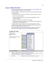
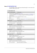
Group
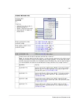
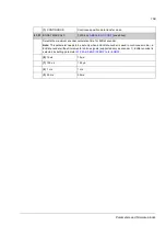
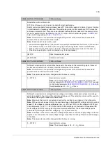
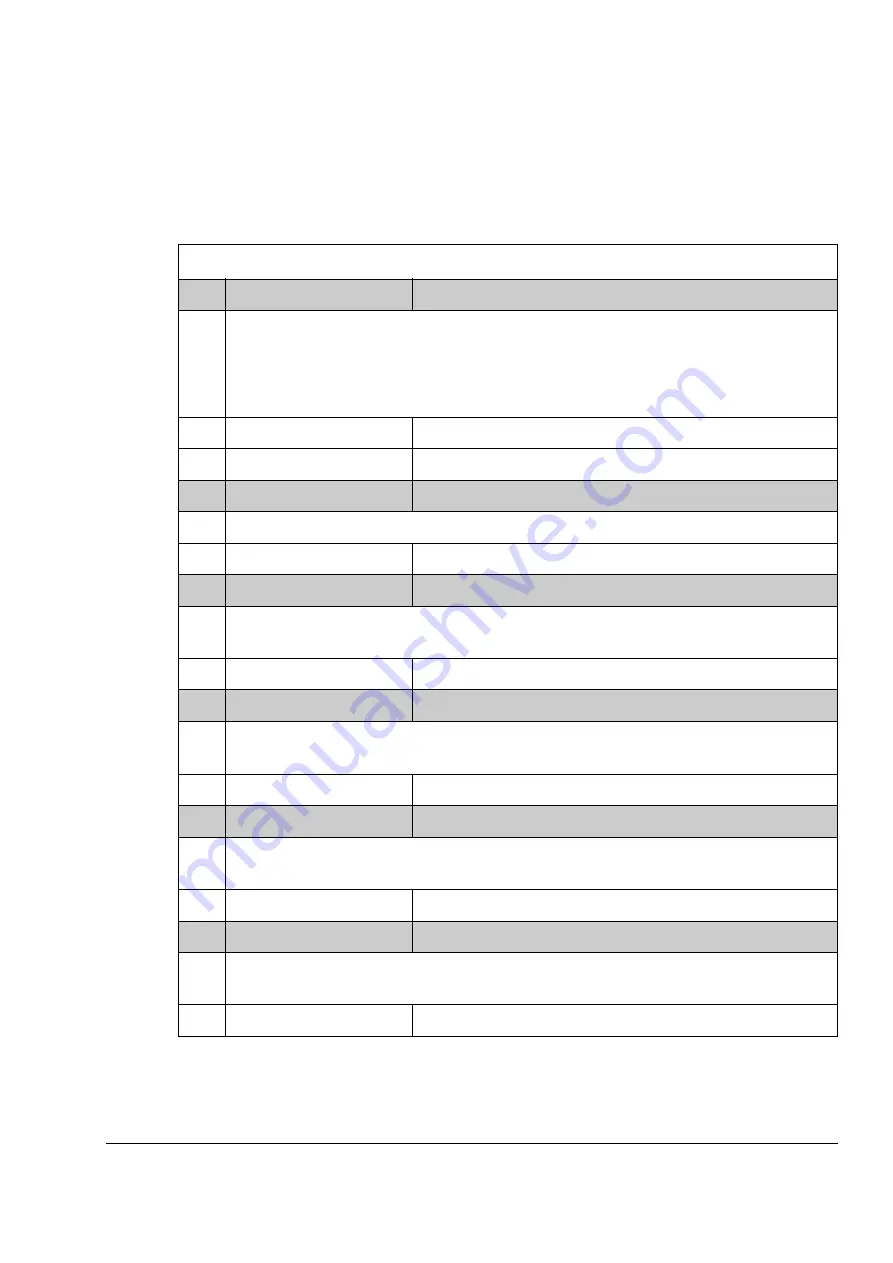
User adjustment of motor model values estimated during ID run. The values can be
entered in either “per unit” or SI.
97
97 USER MOTOR PAR
97.01
USE GIVEN PARAMS
FW block: None
Activates the motor model parameters
…
The value is automatically set to zero when ID run is selected by parameter
. The
values of parameters
are updated according to the motor characteristics identified
during the ID run.
Note:
This parameter cannot be changed while the drive is running.
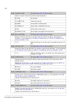
(0)
NO
Inactive.
(1)
USE GIVEN
The values of parameters
…
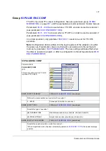
97.02
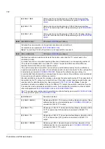
RS USER
FW block: None
Defines the stator resistance
R
S
of the motor model.
0…0.5 p.u. (per unit)
Stator resistance.
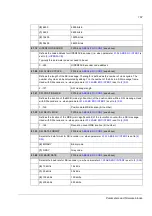
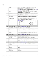
97.03
RR USER
FW block: None
Defines the rotor resistance
R
R
of the motor model.
Note:
This parameter is valid only for asynchronous motors.
0…0.5 p.u. (per unit)
Rotor resistance.
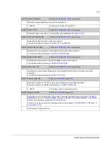
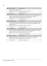
97.04
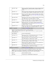
LM USER
FW block: None
Defines the main inductance
L
M
of the motor model.
Note:
This parameter is valid only for asynchronous motors.
0…10 p.u. (per unit)
Main inductance.
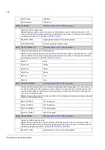
97.05
SIGMAL USER
FW block: None
Defines the leakage inductance
σ
L
S
.
Note:
This parameter is valid only for asynchronous motors.
0…1 p.u. (per unit)
Leakage inductance.
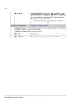
97.06
LD USER
FW block: None
Defines the direct axis (synchronous) inductance.
Note:
This parameter is valid only for permanent magnet motors.
0…10 p.u. (per unit)
Direct axis (synchronous) inductance.
Summary of Contents for ACSM1 Series
Page 1: ...ACSM1 Firmware Manual ACSM1 Speed and Torque Control Program...
Page 2: ......
Page 4: ......
Page 12: ...Table of contents 12...
Page 49: ...Drive control and features 49...
Page 282: ...Standard function blocks 282...
Page 306: ...Application program template 306...
Page 312: ...Control chain block diagrams 312...
Page 331: ...331...
Page 332: ...332...
Page 333: ......

