Standard function blocks
261
FIO_01_slot2
(10085)
Illustration
Execution time
8.6 µs
Operation
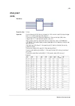
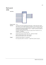
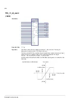
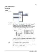
The block controls the four digital inputs/outputs (DIO1…DIO4) and two relay outputs
(RO1, RO2) of a FIO-01 Digital I/O Extension mounted on slot 2 of the drive control unit.
The state of a DIOx conf input of the block determines whether the corresponding DIO
on the FIO-01 is an input or an output (0 = input, 1 = output). If the DIO is an output, the
DOx input of the block defines its state.
The RO1 and RO2 inputs define the state of the relay outputs of the FIO-01 (0 = not
energised, 1 = energised).
The DIx outputs show the state of the DIOs.
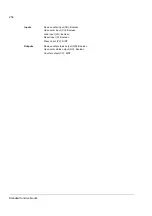
Inputs
Digital input/output mode selection (DIO1 conf … DIO4 conf): Boolean
Digital output state selection (DO1…DO4): Boolean
Relay output state selection (RO1, RO2): Boolean
Outputs
Digital input/output state (DI1…DI4): Boolean
Error output (Error): DINT (0 = No error; 1 = Application program memory full)
FIO_01_slot2
50
TLA1 1 msec
(1)
DIO1 conf
DIO2 conf
DIO3 conf
DIO4 conf
DO1
DO2
DO3
DO4
RO1
RO2
DI1
DI1(50)
DI2
DI2(50)
DI3
DI3(50)
DI4
DI4(50)
Error
Error(50)
Summary of Contents for ACSM1 Series
Page 1: ...ACSM1 Firmware Manual ACSM1 Speed and Torque Control Program...
Page 2: ......
Page 4: ......
Page 12: ...Table of contents 12...
Page 49: ...Drive control and features 49...
Page 282: ...Standard function blocks 282...
Page 306: ...Application program template 306...
Page 312: ...Control chain block diagrams 312...
Page 331: ...331...
Page 332: ...332...
Page 333: ......

