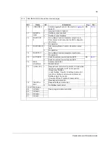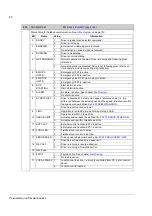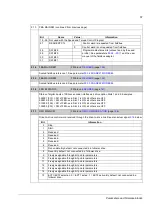
Parameters and firmware blocks
56
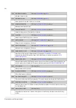
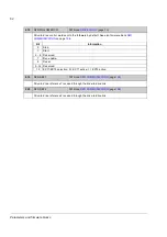
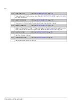
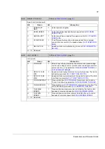
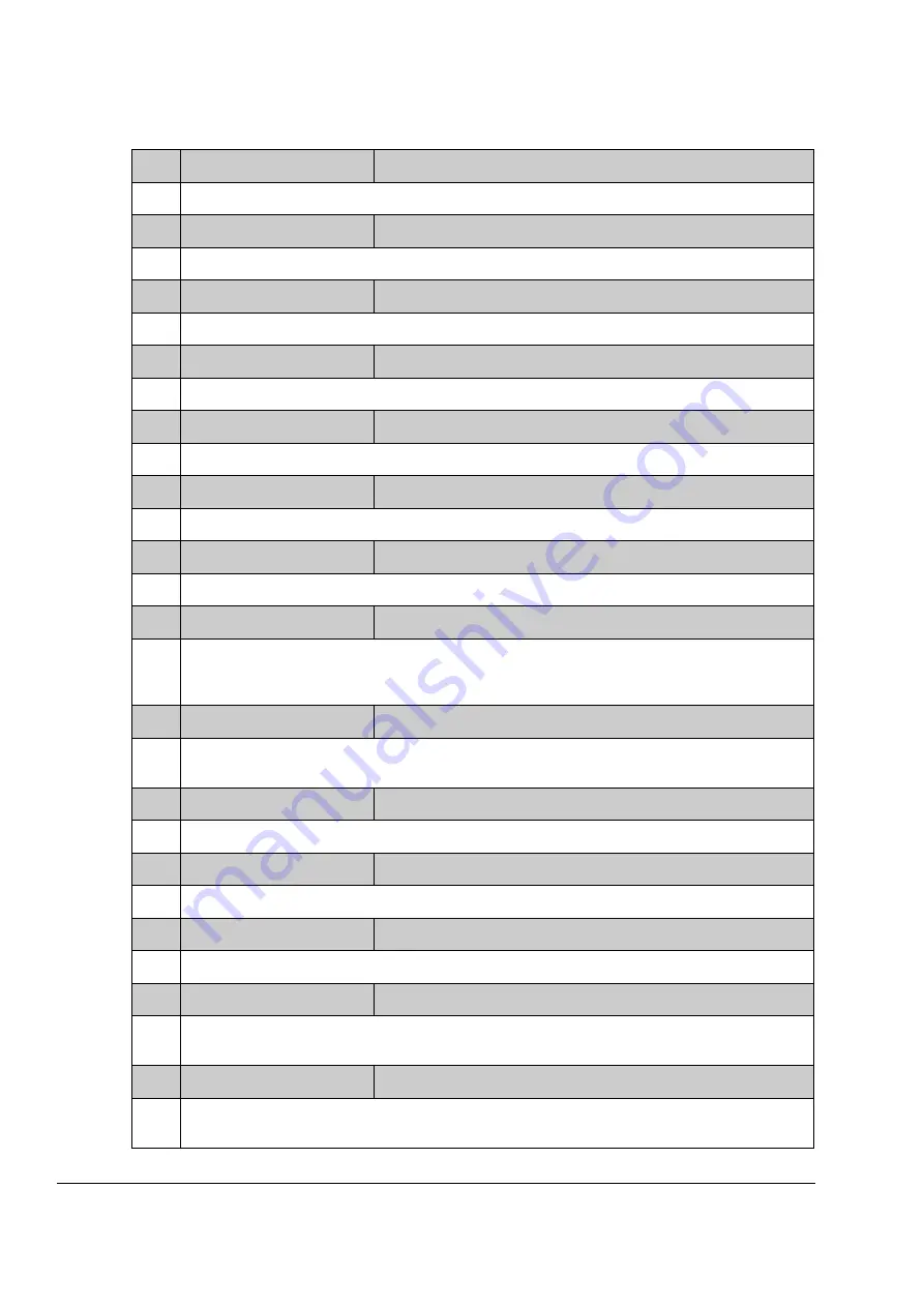
1.10
ENCODER 2 SPEED
FW block:
(page
Encoder 2 speed in rpm.
1.11
ENCODER 2 POS
FW block:
(page
Actual position of encoder 2 within one revolution.
1.14
SPEED ESTIMATED
FW block:
(see above)
Estimated motor speed in rpm.
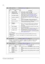
1.15
TEMP INVERTER
FW block:
(see above)
Measured temperature of the heatsink in Celsius.
1.16
TEMP BC
FW block:
(see above)
Brake chopper IGBT temperature in Celsius.
1.17
MOTOR TEMP
FW block:
(page
)
Measured motor temperature in Celsius.
1.18
MOTOR TEMP EST
FW block:
(page
)
Estimated motor temperature in Celsius.
1.19
USED SUPPLY VOLT
FW block:
(page
Either the nominal supply voltage defined by parameter
, or the
automatically determined supply voltage if auto-identification is enabled by parameter
1.20
BRAKE RES LOAD
FW block:
(see above)
Estimated temperature of the braking resistor. The value is given in percent of the temperature the
resistor reaches when loaded with the power defined by parameter
.
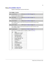
1.21
CPU USAGE
FW block: None
Microprocessor load in percent.
1.22
INVERTER POWER
FW block:
(see above)
Drive output power in kilowatts.
1.26
ON TIME COUNTER
FW block:
(see above)
This counter runs when the drive is powered. The counter can be reset using the DriveStudio tool.
1.27
RUN TIME COUNTER
FW block:
(see above)
Motor run time counter. The counter run when the drive modulates. The counter can be reset using
the DriveStudio tool.
1.31
MECH TIME CONST
FW block: None
Calculated mechanical time constant of the system as identified by the speed control autotuning
routine.
Summary of Contents for ACSM1 Series
Page 1: ...ACSM1 Firmware Manual ACSM1 Speed and Torque Control Program...
Page 2: ......
Page 4: ......
Page 12: ...Table of contents 12...
Page 49: ...Drive control and features 49...
Page 282: ...Standard function blocks 282...
Page 306: ...Application program template 306...
Page 312: ...Control chain block diagrams 312...
Page 331: ...331...
Page 332: ...332...
Page 333: ......

