CONFIGURATION
CUSTOM CONFIGURATION
4 - 14
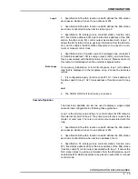
The Type SLC controller is designed to process the function blocks in
ascending numerical order beginning with the lowest numbered one.
For this reason, the lowest block addresses should be assigned to the
function blocks closest to the inputs. This must be done to minimize
loopbacks
. A loopback occurs when the output of a higher num-
bered block is used as an input to a lower numbered block. This situ-
ation requires the controller to process all of the function blocks (a
cycle) more than once before the correct inputs and outputs can be
obtained from blocks that have loopbacks.
NOTE:
Function code 82, S15, autosequencing, can be used to
minimize the effects of loopbacks.
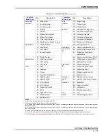
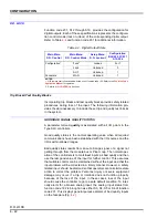
Function Codes
Table
lists function codes that support the Type SLC controller.
The
Function Code Application Manual
provides the specification
lists, block output definitions, and a detailed explanation of the opera-
tion of each function code. The function code manual should be used
in conjunction with this instruction when designing a customized con-
figuration.
Table 4-2. Control Functions
Function
Block Type
No.
Description
Function
Block Type
No.
Description
Station
80
Control station (MFC)
1
Advanced
functions
(continued)
166 Integrator
231 SLC station
1,2
167 Polynomial
Control
function
4
Pulse positioner
168 Interpolator
24
Adapt
169 Matrix addition
156 Advanced PID
170 Matrix multiplication
160 Inferential smith
171 Trigonometric
Batch function 123 Device driver
172 Exponential
161 Sequence generator
173 Power
Advanced
functions
140 Restore
174 Logarithm
152 Model parameter estimator
Computing
1
Function generator
153 ISC parameter converter
2
Manual set constant
154 Adaptive parameter scheduler
3
Lead/lag
162 Digital segment buffer
5
Pulse rate
163 Analog segment buffer
6
High/low limiter
165 Moving average
7
Square root


