DATA MAPPING
DEFAULT DATA MAP
1TGC908004
61
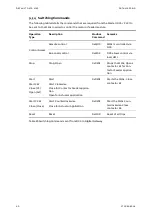
Switching Commands
– Bit Control
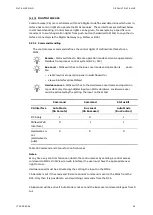
The bit control command gives the possibility to control a starter by setting of a single bit. (In
addition to control a starter by command codes as described in previous chapter.)
16 single command bits are in one Modbus word register. More than one bit can set at simul-
taneously. For example, it is possible to set a M10x to remote and to start it with one Modbus
register write command.
9.2.7.1.
Function Codes
Depending from Modbus function code the commands are handled as described below.
Function 06: Commands
(bit =1) are always sent to M10x, regardless of any change to
the command bit value.
Function 16: Commands
Are sent only when the command bit is toggled, (either 0 to 1
or 1 to 0)
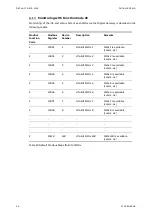
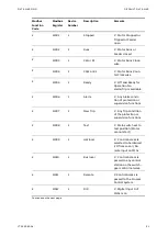
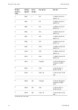
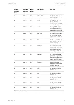
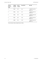
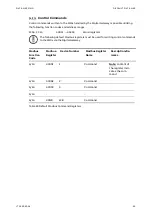
The following tables detail the registers, bit functionalities and show examples of utilizing
Modbus bit commands.
Modbus
Function
Code
Modbus-
Register
Device Number
Modbus Register
Name
Description/Re-
marks
6/16
45001
1
Bit Commands
Note:
content of
the register indi-
cates up to 16 com-
mands
6/16
45002
2
Bit Commands
6/16
45003
3
Bit Commands
6/16
:
:
:
6/16
45128
128
Bit Commands
Table 30 Default Modbus Bit Command Registers
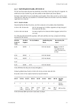
Following table shows how to control a starter by control command bits
Execution order is from highest (bit 15) to lowest bit (bit 0).
Table 31 Default Bit Map Control Commands Low Byte
Bit 07
Bit 06
Bit 05
Bit 04
Bit 03
Bit 02
Bit 01
Bit 00
Register
45001
1
1
1
1
1
1
1
1
Device
Number
Trip
Reset
CA to
Remote
Open
K1
Close
K1
Start
CW
Stop
Start
CCW
Bit Function
Summary of Contents for LVS Digital
Page 1: ... DISTRIBUTION SOLUTIONS LVS Digital with M10x Motor Controller Interface Manual Modbus ...
Page 6: ......
Page 8: ......
Page 78: ......
Page 80: ... Visit us http www abb com mns Document Number 1TGC908004 M0203 ...

