Chapter 3 Software Configuration
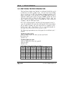
3-10. WATCHDOG TIMER CONFIGURATION
This board has watchdog timer function for monitoring whether the system
is still work or not after a period of time. The user can select watchdog
timer to system reset or NMI (Non Maskable interrupt) depending on the
jumper set in chapter 2. This is defined at I/O port
443H
. When you want to
enable the watchdog timer, please write I/O port
443H
, and then the system
will either reset itself or perform the NMI function. Likewise, when you
want to disable the function, write I/O port
441H
, the system will run the
command to stop the Watchdog function.
In PC 5151 watchdog function, you must write your program so when it
writes I/O port address 443 for enable watchdog and write I/O port address
441 for disable watchdog. The timer
'
s intervals have a tolerance of 25%
(but for level 1 and 2, the tolerance is 4%), so you should program an
instruction that will refresh the timer about every second.
The following program shows you how to program the watch timer in your
program.
Watchdog enable program:
MOVAX, 000FH(choose the values you need; start from 0)
MOV DX, 443H
OUT DX, AX
Watchdog disable program:
MOV AX, 000FH (this value can be ignored)
MOV DX, 441H
OUT DX, AX
The Watchdog Timer control table is as follows:
Level Value
Time/sec
Level Value
Time/sec
1 F
0
9
7
64
2
E
8 10
6 72
3 D
16
11
5
80
4 C
24 12
4
88
5 B
32 13
3
96
6
A
40 14
2 104
7
9
48 15
1 112
8
8
56 16
0 120
Page:3-10
PC 5151 USER
′
S MANUAL
Summary of Contents for PC 5151
Page 1: ...USER S MANUAL PC 5151 Socket 478 P4 P4 M 15 1024X768 Panel PC System Copyright Notice ...
Page 9: ...Chapter 1 Introduction 1 2 CASE ILLUSTRATION PC 5151 USER MANUAL Page 1 3 ...
Page 96: ...Appendix A System Assembly Diagram 2 PC 5151 USER MANUAL Page A 7 ...
Page 98: ...Appendix A System Assembly Diagram 2 PC 5151 USER MANUAL Page A 9 ...
Page 104: ...Appendix A System Assembly Diagram 2 Remove CD ROM PC 5151 USER MANUAL Page A 15 ...
Page 105: ...Appendix A System Assembly EXPLODED DIAGRAM FOR REMOVING MASK Page A 16 PC 5151 USER MANUAL ...
Page 107: ...Appendix A System Assembly Diagram 2 PS 8170A PS 8150A Page A 18 PC 5151 USER MANUAL ...
Page 108: ...Appendix A System Assembly Diagram 3 Diagram 4 PC 5151 USER MANUAL Page A 19 ...
Page 110: ...Appendix B Technical Summary BLOCK DIAGRAM Page B 2 PC 5151 USER MANUAL ...


