Utilities
51
The register unlocking sequence is necessary when writing to
the Preload registers. The following is the procedure of how to
write a value into preload value 1 and 2 register.
1. Write 80H to offset BAR + 0CH.
2. Write 86H to offset BAR + 0CH.
3. Write desired value to preload register. (BAR + 00H or
BAR + 04H)
General Interrupt Status Register
This register is at Base + 08H. Bit 0 is set when the first stage
of down-counter reaches zero.
X
Bit 0 = 0 – No Interrupt
X
Bit 1 = 1 – Interrupt Active
Note
:
This bit is not set in free running mode.
Reload Register
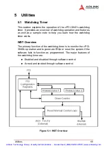
This register is at Base + 0CH. Write 1 to bit 8 will reload the
down-counter’s value. Following is the procedure of how to
prevent a timeout.
1. Write 80H to offset BAR + 0CH
2. Write 86H to offset BAR + 0CH
3. Write a ‘1’ to RELOAD[8] of the reload register
Offset 60 – 61H: WDT Configuration Register
Bit 5 indicates whether or not the WDT will toggle the
WDT_TOUT# pin when WDT times out. (0 = Enabled, 1 = Dis-
abled)
Bit 2 provides two options for prescaling the main down-
counter. (0 = 1ms – 10min, 1 = 1us – 1sec)
Bit [1:0] allows the user to choose the type of interrupt desired
when the WDT reached the end of the first stage without being
reset. (00 = IRQ, 01 = reserved, 10 = SMI, 11 = Disabled)
Note
:
Now, the WDT does not support SMI. IRQ uses APIC 1, INT
10 and it is active low, level triggered.
Artisan Technology Group - Quality Instrumentation ... Guaranteed | (888) 88-SOURCE | www.artisantg.com


