background image


Central Office

Line Simulator

AI-7280


Programmers Guide 


Direct Control 


Advent Instruments Inc. 


Release 2.0a 


Summary of Contents for AI-7280

Page 1: ...Central Office Line Simulator AI 7280 Programmers Guide Direct Control Advent Instruments Inc Release 2 0a ...

Page 2: ...erved Printed in Canada Advent Instruments Inc 111 1515 Broadway Street Port Coquitlam BC V3C6M2 Canada Internet techsupport adventinstruments com sales adventinstruments com Web Site http www adventinstruments com Telephone 604 944 4298 Fax 604 944 7488 ...

Page 3: ...n 12 Set Program Load Address PA offset 12 3 HAL Properties 13 3 1 Overview 13 3 2 ACCAP Properties 14 3 3 BULK Properties 17 3 4 COMM Properties 19 3 5 DATA Properties 21 3 6 DCCAP Properties 25 3 7 DCPROFILE Properties 27 3 8 DIO Properties 29 3 9 DTMF Properties 30 3 10 DTMFCAP Properties 32 3 11 ECHO Properties 34 3 12 FILE Properties 35 3 13 FILTER Properties 37 3 14 FSK Properties 39 3 15 FS...

Page 4: ...pabilities 77 Program Development 78 4 2 Programming Example 78 What is TRsSim 79 Creating a Device Script Project 79 Direct Program Loading 84 4 3 Script Language Basics 85 Process Blocks 85 Function Subroutine Blocks 86 Variables Constants 87 Statements 89 Built in Routines and Properties 92 Appendix A Firmware Revisions 97 Appendix B Property Listing by Index 99 Appendix C Error Codes 104 Appen...

Page 5: ...0 s USB port for direct control however the correct USB drivers are required for this functionality Currently drivers are available for Windows Linux and Apple OS X operating systems Please contact technical support for more information on USB driver availability if you wish to use the USB port This document provides technical information on how the AI 7280 is controlled directly from the RS 232 s...

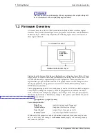
Page 6: ...d into groups of similar function The groups control various settings such as the ringing generator tone generators level meters FSK modulator FSK generator DTMF detector and others From a programming point of view each property can be viewed as a variable or register For example to change the frequency of the ringing generator a command is sent to write a value into the Ring Freq property By writ...

Page 7: ...stored in the HAL property In addition to set and get are other commands used to control the program execution units The AI 7280 contains a number of virtual processors that can be programmed for a wide variety of tasks These are the program execution units shown in the previous figure The program execution units allow the AI 7280 to operate in a semi autonomous manner Programs running on the AI 7...

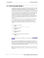
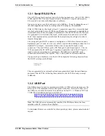
Page 8: ...r Not a CR LF combination Some command examples that can be sent from a terminal program are shown below Note commands are represented by bold face text and must be followed by the CR character The expected response is shown in the line underneath the command Terminal program settings should be 9600 baud 8 data bits 1 stop bit with no flow control 1 Get the software version string HS2 AI 7280 Soft...

Page 9: ...m of three wires are required to make a serial connection They are TX Data pin 2 RX Data pin 3 and Ground pin 5 The AI 7280 can monitor the PC s RTS pin 7 signal and control the state of the CTS pin 8 signal but does not use them to communicate The DSR pin 6 and DTR pin 4 connections are internally tied together Pins 1 and 9 have no internal connection Upon power up or a hardware reset the AI 7280...

Page 10: ......

Page 11: ... execution units See section 2 3 Program Control Commands for more detailed information It is important to note that the same command structure is used for both the RS 232 port and the USB port There is no difference in syntax when using either communication method 2 2 Get Set Commands From a programming point of view the AI 7280 can be represented as a large collection of registers Some of these ...

Page 12: ...ommand must be terminated with a CR character 0Dh before it is processed by the AI 7280 In addition the data returned by the AI 7280 is always terminated with only a CR character In each of the get commands used above the AI 7280 reads the contents of the register and returns its value Reading HN112 returns the frequency of the ringing generator which by default is 22 Hz Register HS2 returns a str...

Page 13: ...and No space characters can be inserted between the register HN112 the equal sign or the value passed 22 otherwise an error message will be returned If setting a numeric value the format for the data must be as follows n n Where n is one or more digits 0 to 9 Examples of valid numeric values are 1 3 1415926 314 159 0 000833 Examples of invalid numeric values are 3 1415926 3 14159e2 000833 If setti...

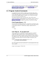
Page 14: ...rror code See Appendix C Error Codes for a listing of the possible error codes and their meaning Clear Program Memory PC This command clears the RAM program memory Programs may be stored and executed out of the internal non volatile flash memory or the RAM If using the RAM to load and execute programs send the PC command before loading a program with the PL command Example PC OK Load Program PL pr...

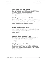
Page 15: ...ing the TRsSim software Example Run program 2 stored in the flash memory on PEU 1 PS1F2 OK Halt Program Execution PH n This command halts program execution for the specified PEU The value n specifies which the PEU to halt If the value zero is passed for n then all PEUs are halted To resume execution use the program resume PR command Example Halt PEU 4 PH4 OK Resume Program Execution PR n Resumes p...

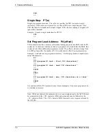
Page 16: ...additional programs are stored The offset value must range from 0 to 4095 and specifies the number of 32 bit words used to offset the program memory Example Load and run two programs in memory The first program has a length of just under 200 characters PC OK PL program 1 text first 100 characters OK PL program 1 text next 100 characters OK PS1M OK PA50 OK PL program 2 text max 123 characters at a ...

Page 17: ...eneration of a single frequency tone TONED Controls the generation of a single frequency tone MFGEN Simplifies generating DTMF or MF tones by providing access to a programmable tone table that specifies frequencies levels and timing for up to 20 different tones NOISE Controls a broadband white noise generator DATA Collection of properties used in defining a bit stream used by the FSK modulator FSK...

Page 18: ...ength supported is 64 characters The null character 0h is used internally to mark the end of a string As such null 0h cannot be used within a character string All of the properties in the following sections are listed in alphabetical order For a listed by ID number see Appendix B Property Listing by Index Note The property descriptions that follow assume an AI 7280 firmware version of at least 4 1...

Page 19: ... continues indefinitely Name ACCAP INDEX ID 184 Type Numeric Description Sets the position in the capture buffer where the next recorded sample is to be stored As samples are collected this property automatically increments by 1 for each sample It also automatically rolls over to zero once the RECLOOPEND property value is exceeded The maximum index value is 229375 Name ACCAP MODE ID 183 Type Numer...

Page 20: ...o the PLAYLOOPSTART value By default PLAYLOOPEND is set to the maximum number of samples allowed in the buffer 229375 Name ACCAP PLAYLOOPSTART ID 212 Type Numeric Description Sets the start position of a range of samples for playback When PLAYINDEX becomes greater than PLAYLOOPEND then PLAYINDEX is set to this value By default PLAYLOOPSTART is set to zero Name ACCAP RECLOOPEND ID 213 Type Numeric ...

Page 21: ...multiply or divide by 3276 8 The 16 bit samples are always sent or received least significant byte LSB first The DC waveform capture buffer contains 24 bit records Each record stores the line voltage and loop current measurements as signed 12 bit values Bits 0 to 11 represent the 2 s complement signed voltage measurement while bits 12 to 23 represent the 2 s complement signed current measurement T...

Page 22: ...scription Sets the minimum amount of space to be maintained in the COMM or USB transmit data buffers This value is only used if the COMM or USB ports are set as the data destination Note If the source is either the AC or DC capture buffers then as the samples are read from the buffers the ACCAP SAMPLEINDEX or DCCAP READINDEX properties are incremented after each read They will wrap to zero when th...

Page 23: ...232 serial communications port check its status send data and receive data The system automatically performs two checks with the communication port First if a line break is detected it resets the baud rate to 9600 and clears the send and receive data buffers A line break also clears bit 0 of the SYSTEM HALTCMDS property Second if a parity framing or receive buffer overrun is detected the entire re...

Page 24: ...ype Numeric r o Description Returns the number of data bytes waiting in the receive buffer Unless SYSTEM HALTCMDS bit 0 is set the command processor routines will automatically remove data bytes from the receive buffer Name COMM RXSTATUS ID 32 Type Numeric r o Description Returns a value representing the serial port status as follows 0 no error 1 parity or framing error detected 2 buffer overflow ...

Page 25: ...ommand processor will automatically remove bytes from the receive data buffer 3 5 DATA Properties These properties are used to control the contents of the FSK transmit data buffer This buffer is used when sending FSK modulated data Any arbitrary pattern of up to 24576 bits can be constructed using these properties See the TONEA properties for information on how to configure and enable the FSK modu...

Page 26: ... stops The string must be an even number of characters otherwise the last character is ignored For example writing 4AE52C adds three bytes left to right with the value of 0x4A 0xE5 and 0x2C to the FSK data buffer Name DATA ADDMARK ID 122 Type Numeric w o Description Writing to this property adds the specified number of mark bits logic high to the FSK data bit buffer The valid range is from 0 to 24...

Page 27: ...r of bits and format of the checksum depends on the XSUMTYPE property value Name DATA BITCOUNT ID 240 Type Numeric r o Description Returns the total number of bits stored in the FSK data buffer Note This property is effectively the same as TONEA NUMBITS Name DATA BITINDEX ID 241 Type Numeric Description Sets an index into the FSK data buffer The index is zero based and its value must range from 0 ...

Page 28: ...till 1200 bps for all the data bits however the 3 stop bits become effectively 1 5 stop bits when viewed at the nominal 1200 baud rate Name DATA PARITY ID 120 Type Numeric Description This property controls the parity setting of any characters or strings added to the FSK bit buffer The value range of settings is 0 8 data bits per character no parity 1 7 data bits per character odd parity 2 7 data ...

Page 29: ...e the checksum value Two settings are supported They are 0 Inverted Modulus 256 used with Telecordia TIA ETSI standards 1 16 Bit CRC x16 x12 x5 1 used with NTT Japan FSK Caller ID Name DATA XSUMVALUE ID 131 Type Numeric Description The current value of the checksum can be read or modified by accessing this property Depending on the XSUMTYPE settings this value ranges from either 0 to 255 8 bit or ...

Page 30: ...his can range from 0 to 8191 As samples are collected this property automatically increments by 1 for each sample It will reset at 8191 to zero on the next sample captured Name DCCAP HEXSTRING ID 172 Type String r w Description Returns a 6 character hexadecimal string representing the voltage and current readings from the buffer location specified by READINDEX The first three nibbles is the curren...

Page 31: ...is 1 100 Accordingly when writing samples into the buffer the desired voltage must be multiply by 100 in order to calculate the 16 bit sample value The play out of samples operates in one of two different modes as set by the MODE property They are MODE 0 standard During play out sample values read from the buffer are used to change both the TELINT VOLTAGE and RING DCLEVEL properties The valid rang...

Page 32: ...value enables continuous play out Setting a value of zero stops any play out in progress As samples are playing this value decrements if positive Name DCPROFILE INDEX ID 216 Type Numeric Description Index position used to access or play out a sample in the buffer This value can range from zero to 229375 All read and writes to the VOLTAGE property increment the INDEX property When play out is runni...

Page 33: ...AGE ID 217 Type Numeric Description Accesses the sample value at the current INDEX position in the buffer Every read or write to this property increments INDEX The sample value is quantized to 16 bits with a 0 01 voltage resolution 3 8 DIO Properties The following properties are used to set the function of the three digital outputs A B C present at the rear panel of the AI 7280 In addition the sta...

Page 34: ... 5 volts 0 fixed at logic low 1 fixed at logic high 3 9 DTMF Properties These properties are used to access the DTMF signal analyzer If enabled the signal analyzer divides the incoming signal into low and high frequency paths using band splitting filters It then measures the frequency and level of each signal path If both low and high group signal levels are above the set minimum threshold and bot...

Page 35: ...n zero value the DTMF detector is enabled If zero then no more measurements are performed and the current measurement values are frozen The value returned by the DIGIT property is frozen as well Name DTMF FREQTIME ID 150 Type Numeric Description Sets the frequency measurement interval in units of ms The valid range is from 2 to 20 As a general rule the longer the measurement interval the more stab...

Page 36: ...ing to occur Up to 63 digits can be captured before the buffer becomes full Once the buffer is full any subsequent digits are lost To qualify as a valid DTMF digit the digit s frequency must match the same DTMF digit three times consecutively Additionally the total signal power measured must be less than twice the low and high group tones combined This improves the talk off performance of the dete...

Page 37: ... is setup as a FIFO If INDEX is zero then the first oldest digit captured can be read Setting INDEX to 1 reads the next captured digit and so on Setting INDEX beyond the number of digits in the buffer will cause all the data read to be zero The maximum value of this property is 62 Name DTMFCAP HIGHFREQ ID 180 Type Numeric r o Description Returns the high group tone frequency in Hz for the digit sp...

Page 38: ...oup tone level falls to less than 1 2 the signal power when the DTMF digit was detected The time value is taken from the TIMER SLOW property If reading the buffer while the digit is still present this value returns a value less than or equal to zero 3 11 ECHO Properties The following properties are used to create transmit signal echoes Up to three echoes can be created with independent delay and g...

Page 39: ...ed by TAPINDEX The gain can range from 100 to 100 A setting of zero turns off the tap Negative gains invert the polarity of the echo and gains between less than 1 or more than 1 represent a loss Name ECHO TAPINDEX ID 156 Type Numeric Description Sets which of the three possible echo taps are adjusted using the TAPDELAY and TAPGAIN properties The valid range is from 1 to 3 3 12 FILE Properties The ...

Page 40: ...ts 0 to 65535 of the 32 bit flash file ID code Name FILE ITEMID ID 22 Type Numeric Description Used in reading a file item Set this property to the item ID number of the desired item Read the ITEMTYPE property to check if it exists within the file Name FILE ITEMNUMBER ID 24 Type Numeric r o Description Returns the value of a numeric file item referenced by the ITEMID property The value returned is...

Page 41: ...ig string unlimited number of characters use ITEMSTRING to read 5 binary data array cannot be read 3 13 FILTER Properties Optional filters may be placed before the various signal measurement meters The following properties set the filter type of which some may have adjustable corner or center frequencies Up to two notch filters can be applied before the signal meter s secondary level meter The fol...

Page 42: ... resets this value to 1000 Hz Name FILTER N1FREQ ID 78 Type Numeric Description Sets the center frequency for the first of two secondary notch filters The valid frequency range is from 20 to 10000 Hz Note that writing to the NUMNOTCH property resets this value to 1000 Hz Name FILTER N2FREQ ID 79 Type Numeric Description Sets the center frequency for the second of two secondary notch filters The va...

Page 43: ...ejects low group tones 9 C message weighting filter 10 ITU O 41 weighting filter 3 14 FSK Properties The following collection of properties provides access to the FSK decoder The decoder converts a FSK modulated data stream back into a series of bytes The FSK signal is assumed to conform to either Bell 202 or V 23 standards with the data bytes encoded as 1 start bit 8 data bits and 1 or more stop ...

Page 44: ...Description Returns the number of bytes decoded and stored in the FSK data buffer After decoding a byte the COUNT value is incremented by one The valid range for COUNT is from 0 to 2047 Normally this value should be set to zero before enabling the FSK decoder Once the first byte is received the COUNT value returns 1 If setting the COUNT property to N the next byte received can be read using an IND...

Page 45: ...bit index equals or exceeds the BITINDEX value in the table then the current mark and space signal level is multiplied by the corresponding GAIN value in the table row Following this change the pointer is incremented to the next row in the table In this manner up to four level changes may be programmed during the generation of a FSK modulated signal When using these properties please note All gain...

Page 46: ...quency or phase measurements of a signal or return the telephone interface line voltage and loop current measurements Optional filters may be placed before the AC level and frequency measurements by using the FILTER properties In addition a secondary level measurement may be preceded by up to two programmable notch filters These are normally used in performing THD N measurements The telephone inte...

Page 47: ...iption Returns the current telephone interface line voltage measurement in units of volts The DCSMOOTHING property sets the amount of averaging applied to this measurement Name MEASURE LOOPCURR ID 72 Type Numeric r o Description Returns the current telephone interface loop current measurement in units of mA The DCSMOOTHING property sets the amount of averaging applied to this measurement Name MEAS...

Page 48: ... Name MEASURE PHASELEVEL ID 209 Type Numeric r o Description Returns the RMS level of the phase reference signal as selected by the SOURCE PHASEREF property The SMOOTHING property determines the amount of averaging applied to this measurement Name MEASURE SMOOTHING ID 66 Type Numeric Description Sets the smoothing factor used with the various RMS level meters The valid range is from 0 5 to 0 99995...

Page 49: ...3 Type Numeric Description Sets the duration of the metering pulse tone burst in units of ms The valid range is from 1 to 1 000 000 ms To generate a continuous tone set this value greater than the REPEAT value If the DURATION is equal to the REPEAT value the generator produces a continuous tone however once the pulse duration has elapsed the tone generator s phase is reset to 0 degrees and the nex...

Page 50: ... 7 31 32 33 34 35 1007 8 8 36 37 38 39 40 1008 9 9 41 42 43 44 45 1009 10 0 46 47 48 49 50 1010 11 51 52 53 54 55 1011 12 56 57 58 59 60 1012 13 A 61 62 63 64 65 1013 14 B 66 67 68 69 70 1014 15 C 71 72 73 74 75 1015 16 D 76 77 78 79 80 1016 17 E 81 82 83 84 85 1017 18 F 86 87 88 89 90 1018 19 G 91 92 93 94 95 1019 20 H 96 97 98 99 100 1020 Note that the off time column is only relevant when two o...

Page 51: ...applications this represents the ROW tone frequencies Name MFGEN FREQADJUST2 ID 136 Type Numeric w o Description Writing to the FREQADJUST2 property causes the frequency of tone 2 for the first 16 symbols to be adjusted by the specified percentage from their current value For DTMF applications this represents the COLUMN tone frequencies Name MFGEN FREQOFFSET1 ID 136 Type Numeric w o Description Wr...

Page 52: ...els to the same value The valid range for the level is from 0 to 4 0 Vrms Name MFGEN LEVEL1 ID 230 Type Numeric w o Description Writing to this property sets the level of tone 1 for the first 16 symbols to the specified value in units of Vrms For DTMF applications this is the ROW tone level The valid range for the tone level is from 0 to 4 0 Vrms Name MFGEN LEVEL2 ID 231 Type Numeric w o Descripti...

Page 53: ...the tone generator by writing a non zero value to the ACTIVE property Name MFGEN SYMBOL ID 139 Type Numeric w o Description Writing to this property specifies the next symbol to generate The valid range for this property is from 1 to 20 Start the symbol by writing a non zero value to the ACTIVE property Note that the STRING property takes precedence over this property Do not write to it before sta...

Page 54: ...ook state the ringing resumes This operation can be altered with the RING TRIP property which causes the ring generator to turn off upon detecting an off hook condition Note the ringing generator can produce a maximum of 80 Vrms when using the Sine wave shape and a nominal DC offset voltage level of 48 Volts If higher crest factor wave shapes or different DC offset voltages are selected the ringin...

Page 55: ...ets the ringing level from 0 Vrms to 80 Vrms Name RING PHASE ID 114 Type Numeric Description Reading this property returns the current ring generator phase angle between 0 and 360 degrees Writing to this property sets the current phase angle Note if ringing is not active reading this property returns 0 Name RING TRIP ID 207 Type Numeric Description Controls the state of the ringing generator when ...

Page 56: ... then the action is triggered and it executes If multiple action records are created using the same ATCOUNT and ATTIMER values the actions are executed in the order they were created Action records are created when writing to the ACTION property The value written to ACTION determines the action taken It must be either A valid HAL register number When the action triggers it performs a write to the ...

Page 57: ...ER ID 247 Type Numeric Description Sets the value that TIMER SLOW must be greater or equal to in order to trigger an action Name SCHEDULER COUNT ID 249 Type Numeric r o Description Returns the number of actions waiting to be triggered As actions are triggered this value counts down It returns zero when all actions have been triggered Name SCHEDULER PARAMETER ID 248 Type Numeric Description Sets th...

Page 58: ...erties The following four properties select what signal source is routed to the signal meter signal analyzer rear panel BNC output and the phase meter reference channel Name SOURCE ANALYZER ID 64 Type Numeric Description Sets the source of the signal routed to the signal analyzer DTMF FSK Decoder waveform capture as follows 0 off 1 telephone interface both transmit and receive signals 2 telephone ...

Page 59: ...ETER ID 63 Type Numeric Description Sets the source of the signal routed to the signal meter as follows 0 off 1 telephone interface both transmit and receive signals 2 telephone interface hybrid output rejects signals transmitted by the AI 7280 3 rear panel BNC input connector 4 tone generators tone A B C D MF and FSK generator waveform playback 5 telephone interface transmit signal applied to the...

Page 60: ...senting the following Bit 0 Set if noise generator enabled Bit 1 Set if ToneA generator enabled Bit 2 Set if ToneB generator enabled Bit 3 Set if ToneC generator enabled Bit 4 Set if ToneD generator enabled Bit 5 Set if FSK Generator is active Bit 6 Set if MF DTMF generator active Bit 7 Set if ringing generator is active Bit 8 Set if AC Playback is active Bit 9 Set if DC profile playback is active...

Page 61: ...U 3 status is NOT zero Bit 12 Set if PEU 4 status is NOT zero Bit 13 Set if PEU 5 status is NOT zero Bit 14 Set if PEU 6 status is NOT zero Bit 15 Set if any PEU is in the ERROR state 3 25 SYSTEM Properties The following properties perform a wide range of system related tasks These included returning firmware version information controlling error conditions and managing system interrupt flags Name...

Page 62: ... that it is delayed by the de bounce period used to qualify the hook status Bit 1 On Hook Detect Set when the loop current falls below the off hook threshold Note that it is delayed by the de bounce period used to qualify the hook status Bit 2 Digital Input A Set when the rear panel digital input pin changes state Note that pulses shorted than 200 us may not be detected Bit 3 Digital Input B Set w...

Page 63: ... 0 Command processing from both serial and USB is enabled 1 Command processing from serial port is disabled 2 Command processing from USB port is disabled 3 Command processing from both ports is disabled Note if a line break is detected on the serial port then command processing will be resumed if currently disabled If the USB port goes into reset or is un plugged then command processing is resume...

Page 64: ...ms a low level system call Do not use Name SYSTEM SUBINDEX ID 6 Type Numeric Description Accesses a low level system call parameter Do not use Name SYSTEM SUBINTEGER ID 8 Type Numeric Description Accesses a low level system call parameter Do not use Name SYSTEM SUBSTRING ID 9 Type String Description Accesses a low level system call parameter Do not use Name SYSTEM SUBVALUE ID 7 Type Numeric Descri...

Page 65: ...nsmit signals from the receive signals on the telephone line For maximum rejection of transmit signals it should be set to match the impedance of the connected terminal equipment device The following settings are available 0 600 ohms 1 900 ohms 2 TBR 21 3 optional impedance only available if installed in the AI 7280 Name TELINT BNCINGAIN ID 59 Type Numeric Description Sets the gain from the BNC in...

Page 66: ...s setting is forced to a value of 1 Once ringing stops it is returned to the previous value It is possible to change this property once ringing has started Though when ringing stops the setting is returned to the prior value Name TELINT HOOKDETECT ID 54 Type Numeric r o Description This read only property returns the off hook detection status If a connected TE is off hook a value of 1 is returned ...

Page 67: ... pair of conductors on the RJ 11 jack These two pins are not connected to the telephone interface Name TELINT MEASRANGE ID 56 Type Numeric Description Sets the AC signal measurement range If set to zero default the maximum AC signal voltage that can be measured is approximately 5 Vrms Writing a non zero value to this property allows AC signals of up to 100 Vrms to be measured Name TELINT OSI ID 50...

Page 68: ...ts ms and must be in the range of 0 to 20 Writing to this property starts the process of ramping the line voltage towards the value set by VRAMPRATE When the line voltage reaches the destination voltage this property value is reset to zero Writing zero at any time stops the change in the line voltage Note if high voltage slew rates are specified and a line polarity change is required negative VRAM...

Page 69: ...ired However its value is time corrected for the de bounce period Name TIMER ONHOOK ID 46 Type Numeric Description This property gets set to the value of the SLOW timer when the telephone interface line status goes on hook Note that this property does not get updated until after on hook the de bounce period has expired However its value is time corrected for the de bounce period Name TIMER ROLLAT ...

Page 70: ...OLLCOUNT to incremented by one Name TIMER SYSTEM ID 43 Type Numeric Description Secondary slow updating timer This timer counts up every 200 microseconds to a maximum of 100 000 seconds It can be written to with any value in the range of 0 to 100 000 Note that as the timer value increases the precision by which it can be read decreases This is due to limitations in the 32 bit floating point format...

Page 71: ...tone of arbitrary level and frequency It is more flexible than tone generators B C or D in that it can be either FSK or AM modulated The MODULATION parameter determines the operating mode For AM modulation tone generator B is the modulating signal while the TONEA FREQ property sets the carrier frequency The FSK modulator operates with either an internal data source the DATA properties or an extern...

Page 72: ...e FSK properties must be set along with the modulation mode before writing a non zero value otherwise the FSK modulator will not start Also if the FSK modulator is run in single shot mode not continuous the ENABLE property is not set to zero once the FSK ends It must be manually reset to zero In addition when the FSK signal ends the tone level properties are forced to zero Name TONEA FREQ ID 96 Ty...

Page 73: ...mum number of bits in the buffer Writing to this property changes the index pointer and effects which data bits are being generated To start the FSK data at the first bit set this value to zero before writing a non zero value to the ENABLE property Name TONEA FSKCONTINUOUS ID 104 Type Numeric Description Writing a non zero value to this property before the FSK modulator is enabled causes the FSK m...

Page 74: ...ID 106 Type Numeric Description The modulation mode of the tone generator is set by this property The supported modes are 0 Single Tone 1 FSK Modulation 2 Amplitude Modulation Tone B is the modulating source 3 FSK Modulation External Digital Input A If in the amplitude modulation mode tone generator B does not produce any output except as the modulating source for tone A Name TONEA PHASE ID 109 Ty...

Page 75: ...anged to either triangle square or a user defined wave shape Note that if Tone A is set for AM modulation then this tone generator becomes the modulation source The depth of the modulation is set by TONEA AMDEPTH and TONEB LEVEL has no effect Name TONEB ENABLE ID 80 Type Numeric Description Writing a non zero value enables the tone generator Writing zero turns off the tone generator Note if ringin...

Page 76: ...ator can output a single tone of arbitrary level and frequency While the default wave shape is sine it may be changed to either triangle square or a 256 point user defined wave shape Note if this tone is enabled the MF generator cannot be enabled Changing any TONEC property except PHASE disables the MF generator if it is active Name TONEC ENABLE ID 85 Type Numeric Description Writing a non zero va...

Page 77: ...ined wave shape please contact technical support 3 32 TONED Properties This signal generator can output a single tone of arbitrary level and frequency While the default wave shape is sine it may be changed to either triangle square or a 256 point user defined wave shape Note if this tone is enabled the MF generator cannot be enabled Changing any TONED property except PHASE disables the MF generato...

Page 78: ... defined Note the LEVEL property is only calibrated for the sine wave shape For information on how to program the user defined wave shape please contact technical support 3 33 USB Properties The following properties are used to control the USB port check its status send data and receive data Name USB ENABLE ID 36 Type Numeric Description Enables or disables the USB port Writing a 0 disables the po...

Page 79: ...e space left in the buffer Name USB SENDSTRING ID 40 Type Numeric w o Description Similar to the SENDBYTE property but instead sends a character string to the transmit buffer The TXFREE property should be checked prior to sending the string as there may not be any free space left in the buffer Name USB STATUS ID 42 Type Numeric r o Description Returns the status of the USB connection as follows 0 ...

Page 80: ...The properties to receive data bytes should not be accessed unless the SYSTEM HALTCMDS property has bit 2 set Otherwise the command processor will automatically remove bytes from the receive data buffer 76 AI 7280 Programmers Guide Direct Control ...

Page 81: ...levels Simple tasks can be performed by the AI 7280 PEUs while the higher level test control tasks performed by the PC Capabilities The AI 7280 contains six program execution units PEU Each one can be thought as a very simple processor executing instructions that manipulate HAL properties in order to perform user specified tasks The operation of each PEU is controlled by commands sent to the AI 72...

Page 82: ...xecution of the program by simply sending an appropriate command The object code can be downloaded into the AI 7280 s RAM by using the provided Win32 DLL The object code can be downloaded into the AI 7280 s RAM manually by sending the appropriate PC PL and PA commands The following section provides an example of creating a program for the AI 7280 by using the TRsSim software Note An older PC softw...

Page 83: ...wever TRsSim only supports one project as the active project at a time It is only the active project that is compiled and executed Step 1 From the VIEW menu in TRsSim select the SCRIPT EDITOR command This command opens the scripting editor window from where all projects are created and managed The window shows one of three different views as selected by the tabs located in the top right corner The...

Page 84: ...e active project The text editor displays the default source code module called Start From this point the program source code can be created All scripting programs are composed into one of three different types of blocks They are PROCESS blocks FUNCTION blocks or SUB blocks When writing programs for the AI 7280 at least one process block must exist This is from where program execution starts TRsSi...

Page 85: ...ts how long to wait at a single frequency point and the tone level during the sweep Next is the With ToneA statement which tells the compiler that any properties that start with a dot belong to tone generator A This is really a short cut for reducing the amount of typing needed Instead of having to type the full name of a property like ToneA Enable using a with statement simplifies this to just En...

Page 86: ...and begins its execution While a program runs on the AI 7280 the start button on the tool bar green arrow is disabled However the pause button blue bars and stop button red box are enabled Clicking on either pauses or stops the program execution respectively The program can be started or stopped as many times as desired If any changes are made to the program it is recompiled automatically the next...

Page 87: ...re is only one process block in the program the name in this field does not matter However if there are more than one process blocks then this field determines which one is executed on program start Startup process number Sets which one of the 6 program execution units PEUs within the AI 7280 is used to execute the program Access system properties If checked the compiler allows reading or writing ...

Page 88: ...ntrol aspects of the AI 7280 Run with system launcher This setting is only applicable when writing programs and being connected to the AI 80 Direct Program Loading While the TRsSim software can be used to compile an AI 7280 device script in some situations it may be desirable to manage the loading of the programs and their execution from another application Applications can load and control AI 728...

Page 89: ...ew of the scripting language used by the TRsSim compiler For more a complete reference please consult the Language Reference Guide document included with the TRsSim software It is important to note that the compiler generates programs for execution either within the TRsSim software itself or within a device like the AI 7280 The two compiler targets while virtually the same have some differences be...

Page 90: ... do not return any data while functions return either a numeric or string data type Subroutines are initiated by the CALL command while functions may be part of an expression The syntax for the function and subroutine blocks are as follows FUNCTION type identifier type identifier type identifier statements EXIT FUNCTION WITH expression END FUNCTION WITH expression SUB identifier type identifier ty...

Page 91: ...he function ends The WITH keyword is optional and if missing the function will return either zero or an empty string depending on the function s data type An END SUB or END FUNCTION statement must be included to mark the end of the routine Once the program reaches this point control is passed back to the calling section To exit prematurely from a routine use the EXIT SUB or EXIT FUNCTION statement...

Page 92: ... can only be accessed from within the function or subroutine No other routine can access the variable Normally all variables are localized to the program execution unit they execute in As such each process has its own instance of all declared variables To share data between processes use the IMPORT and EXPORT modifiers They force the compiler to allocate the variable into a data pool that is share...

Page 93: ...mmediately exits the loop FOR NEXT Usage FOR var exp1 TO DOWNTO exp2 STEP exp3 statements EXIT FOR NEXT var Where var is a variable modified by the FOR NEXT loop Must be of a numeric data type exp1 is an expression that represents the initial value for var The expression must evaluate to a numeric value exp2 is an expression that represents the value compared to the var If counting up TO keyword t...

Page 94: ... same value the statements following the CASE keyword are executed When another CASE keyword is encountered or the END SELECT statement program execution jumps to the first statement following END SELECT Optionally the keyword ELSE may be used instead of an expression It always evaluates to true and any following statements are executed if none of the previous CASE expressions matched CALL Usage C...

Page 95: ...to the beginning of the same or different process block When the optional IF keyword is used then the provided expression must evaluate to a non zero value in order for execution to transfer to the specified process If the expression evaluates to zero then execution continues to any following statements LABEL Usage LABEL identifier The LABEL statement marks a position within the current PROCESS SU...

Page 96: ...eration Functions ABS Absolute value Usage NUMERIC ABS NUMERIC Returns the absolute value of the passed numeric value ASC Convert to ASCII code Usage NUMERIC ASC STRING NUMERIC Returns the ASCII character code of a single character contained in the string at the position of the passed numeric parameter For example ASC Hello 2 returns the ASCII code for the second character which is e or 101 CHR Co...

Page 97: ...Usage STRING HEX NUMERIC1 NUMERIC2 Returns a string representing the hexadecimal value of the first numeric value The second numeric value specifies how many characters are returned by the function INT Convert to integer Usage NUMERIC INT NUMERIC Returns the integer portion of the passed number This is the largest integer value less than the passed number For example Int 3 99 returns 3 Int 3 01 re...

Page 98: ... directly to either the local PEU s data pool or the data pool shared by all PEUs The first parameter is the byte value to store and the second value specifies where in the data pool to store the byte The valid locations are as follows Values 0 to 1199 Byte written to local data pool Values 10000 to 11199 Byte written to shared data pool WAIT Suspend program execution Usage CALL WAIT EXPRESSION Te...

Page 99: ...er is never set when the ME TIMER reaches zero ME TIMER is then used by polling its value The second method for using the ME TIMERFLAG property is to set it to a positive value Then when ME TIMER reaches zero the PEU s interrupt flag register gets bitwise OR ed with ME TIMERFLAG A program then uses the HALTUNTIL function to resume execution when ME TIMER reaches zero or when any system wide interr...

Page 100: ......

Page 101: ... to known bugs Any time new properties are added or their capabilities expanded all attempts are made to preserve backwards compatibility This permits the firmware to be upgraded anytime without concern for breaking applications that were developed with older versions of the firmware For the most current listing of the AI 7280 s firmware s revision history please see http www adventinstruments com...

Page 102: ......

Page 103: ...t Numeric Read Only 14 System FlagGet Numeric Read Only 15 System FlagSet Numeric Write Only 16 System FlagClear Numeric Write Only 17 System HaltCmds Numeric 18 System Options Numeric Read Only 19 File IDlow Numeric 20 File IDhigh Numeric 21 File Exist Numeric Read Only 22 File ItemID Numeric 23 File ItemType Numeric Read Only 24 File ItemNumber Numeric Read Only 25 File ItemString String Read On...

Page 104: ...ic 67 Measure Level Numeric Read Only 68 Measure Freq Numeric Read Only 69 Measure NotchLevel Numeric Read Only 70 Measure DcSmoothing Numeric 71 Measure LineVoltage Numeric Read Only 72 Measure LoopCurrent Numeric Read Only 73 Measure Unbalance Numeric Read Only see 209 to 211 for additional Measure properties 74 Filter Type Numeric 75 Filter HiFreq Numeric 76 Filter LoFreq Numeric 77 Filter NumN...

Page 105: ...e Numeric Write Only 126 Data AddChar Numeric Write Only 127 Data AddString String Write Only 128 Data AddXsum Numeric Write Only 129 Data XsumEnable Numeric 130 Data XsumType Numeric 131 Data XsumValue Numeric 132 Data AddHexString String Write Only see 222 237 to 242 for additional Data properties 133 MFGen Index Numeric 134 MFGen Value Numeric 135 MFGen Level Numeric 136 MFGen FreqAdjust Numeri...

Page 106: ...Read Only 181 DTMFCap StartTime Numeric Read Only 182 DTMFCap StopTime Numeric Read Only 183 AcCap Mode Numeric 184 AcCap Index Numeric 185 AcCap Count Numeric 186 AcCap SampleIndex Numeric 187 AcCap Sample Numeric 188 AcCap PlayIndex Numeric 189 AcCap PlayCount Numeric see 212 to 215 for additional AcCap properties 190 Bulk Source Numeric 191 Bulk Dest Numeric 192 Bulk Length Numeric 193 Bulk Spa...

Page 107: ...ollAt Numeric 229 Timer RollCount Numeric see 43 to 48 for additional Timer properties 230 MFGen Level1 Numeric Write Only 231 MFGen Level2 Numeric Write Only 232 MFGen FreqAdjust1 Numeric Write Only 233 MFGen FreqAdjust2 Numeric Write Only 234 MFGen FreqOffset1 Numeric Write Only 235 MFGen FreqOffset2 Numeric Write Only 236 MFGen Reset Numeric Write Only see 133 to 141 for additional MFGen proper...

Page 108: ...14 The non volatile flash memory write command does not contain valid data 115 A write operation failed with the non volatile flash memory command The physical memory device may be bad or the sector had not been erased 116 An erase operation failed with the non volatile flash memory command The physical memory device may be bad 120 Invalid program execution unit PEU number specified Valid numbers ...

Page 109: ...alue of a HAL register which does not exist 12xxxx Attempting to set the value of a HAL register which is read only 13xxxx Attempting to set the value of a HAL register with an incompatible data type Mismatch between numeric and character string data types 15xxxx Attempting to get the value of a HAL register which does not exist 17xxxx Attempting to get the value of a HAL register which is write o...

Page 110: ......

Page 111: ...Questions techsupport adventinstruments com Sales Inquiries sales adventinstruments com In North America Tel 604 944 4298 Fax 604 944 7488 Mail Advent Instruments Inc 111 1515 Broadway Street Port Coquitlam BC V3C6M2 Canada In Asia Tel 852 8108 1338 Fax 852 2900 9338 Mail Advent Instruments Asia Ltd Unit No 7 9 F Shatin Galleria 18 24 Shan Mei Street Fotan Shatin N T Hong Kong AI 7280 Programmers ...

Page 112: ......

Page 113: ...f Caller ID or SMS DLL the checksum is a byte value sent after the message data It represents the two s complement sum of all the message byte values Used for error detection dBm Unit of signal power level Calculated as 10 times the base 10 logarithm of the ratio of the signals power relative to 0 001 Watt For example 1 mW 0 dBm 100 mW 20 dBm For most telephone applications signal levels expressed...

Page 114: ... in the range of 100 ms to 1000 ms FSK Frequency Shift Keying A method of signal modulation for data transmission For Caller ID and SMS applications a tone s frequency is shifted between two values representing either a mark or space bit TE Terminal Equipment A device connected to the telephone network Also commonly referred to as a CPE Customer Premise Equipment MDMF Multiple Data Message Format ...

Page 115: ...ialing which expresses the rate of dialing pulses A dialing pulse is a short interval of time in which the TE goes on hook and then returns to the off hook state The most common pulse rate in use is 10 pps however various PSTN s may require faster or slower rates for dialing PSTN Public Switched Telephone Network A network of devices allowing a TE to establish a connection to another device for th...

Page 116: ...every 8 bit data byte transmitted via a FSK modulated signal is preceeded with a single start bit The start bit is always represented with the space tone THD N Total Harmonic Distortion plus Noise A measurement normally expressed as a ratio of the signal s harmonic distortion level plus noise to the total signal level TL Transfer Layer A layer in the SMS protocol stack providing a service to the S...

Page 117: ...he mark signal level is higher than the space level Type I Caller ID data transmission occurring while the TE is in the on hook state Type II Caller ID data transmission occurring while the TE is in the off hook state V 23 An FSK modulation standard that uses 1300 Hz for the mark tone frequency and 2100 Hz for the space tone frequency The baud rate used is 1200 bits per second ...

Reviews: