Chapter 7
7-81
Programming Examples
Analyzer System Setup Examples
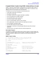
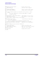
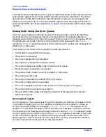
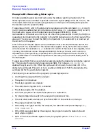
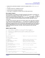
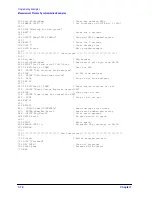
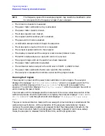
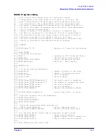
Example 5B: Reading Calibration Data
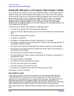
This example demonstrates:
• how to read measurement calibration data out of the network analyzer
• how to read it back into the analyzer
• how to determine which calibration is active
The data used to perform measurement-error correction is stored inside the analyzer in
one (or more) of twelve calibration-coefficient arrays. Each array is a specific error
coefficient, and is stored and transmitted as an error-corrected data array. Each point is a
real/imaginary pair, and the number of points in the array is the same as the number of
points in the sweep. The five data formats also apply to the transfer of
calibration-coefficient arrays. Your analyzer’s user’s guide contains information on the
storage locations for calibration coefficients and different calibration types.
A computer can read out the error coefficients using the commands
OUTPCALC01
,
OUTPCALC02
,…through
OUTPCALC12
. Each calibration type uses only as many arrays as
required, beginning with array 1. Hence, it is necessary to know the type of calibration
about to be read out. Attempting to read an array not being used in the current calibration
causes the
“REQUESTED DATA NOT CURRENTLY AVAILABLE”
warning.
A computer can also store calibration coefficients in the analyzer. To do this, declare the
type of calibration data about to be stored in the analyzer just as if you were about to
perform that calibration. Then, instead of calling up different classes, transfer the
calibration coefficients using the
INPUCALCnn;
commands. The variables
nn
are a data pair
appended to the command representing a calibration number from
01
through
12
. When
all the coefficients are stored in the analyzer, activate the calibration by issuing the
mnemonic
SAVC;
, and trigger a sweep on the analyzer.
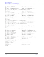
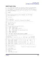
This example reads the calibration coefficients into a very large array, from which they can
be examined, modified, stored, or put back into the instrument. If the data is to be directly
stored onto disk, it is usually more efficient to use FORM 1 (analyzer's internal-binary
format), and to store each coefficient array as it is read in.
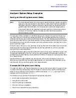
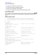
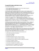
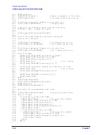
The following is an outline of the program's processing sequence:
• An I/O path is assigned for the analyzer.
• A binary path is assigned.
• The system is initialized.
• The calibration types and number of arrays are defined.
• The integer variables for reading the headers are defined.
• The calibration type and number of arrays are read by the controller.
• The output is formatted in FORM 3.
• The number of points in the trace is read.
• The memory is allocated for the calibration arrays.
• Each calibration array is requested from the analyzer.
• Header information is read with a binary I/O path.
Summary of Contents for 8719ES
Page 15: ...1 1 1 Alphabetical Command Reference ...
Page 293: ...2 1 2 Introduction to Instrument Control ...
Page 310: ...3 1 3 GPIB Programming ...
Page 334: ...4 1 4 Reading Analyzer Data ...
Page 343: ...5 1 5 Data Processing Chain ...
Page 350: ...6 1 6 Error Reporting ...
Page 364: ...7 1 7 Programming Examples ...
Page 502: ...A 1 A Preset Conditions ...
Page 517: ...B 1 B Command Listings ...

