AirM2M_ESP8266 WiFi module user manual V3.2
Shanghai AirM2M Communication Technology Co., Ltd
http://www.airm2m.com
Page 10
Notes:
1)There are 3 serial ports(uarts):
UART0(U0RXD
、
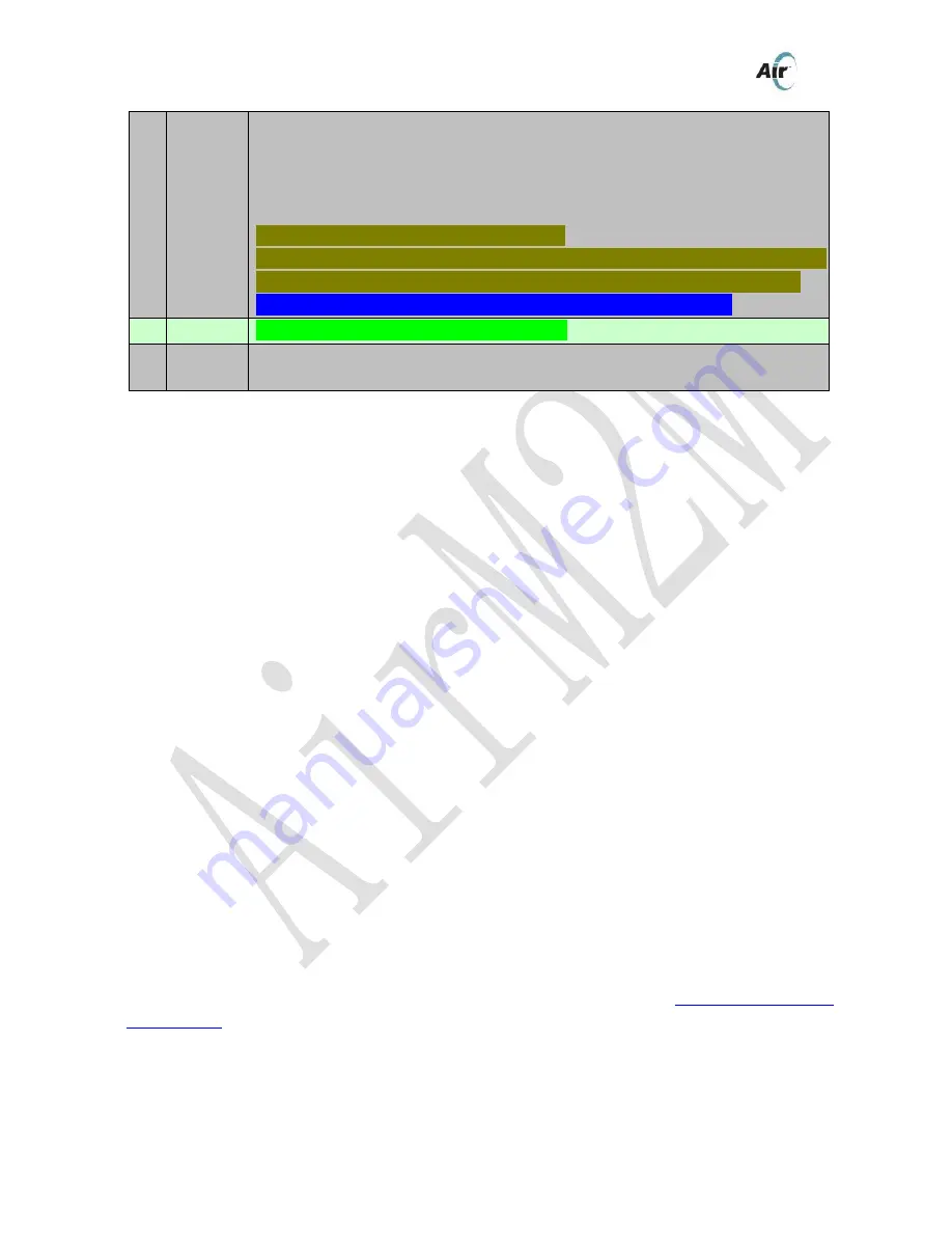
U0TXD)is an uart for firmware download. Marked in
red
in table3.
UART1(U1RXD
、
U1TXD
、
U1CTS
、
U1RTS
、
U1DTR
、
U1RI) is an uart for AT commands /data.
Debug_UART(Debug_TXD)is a debug uart for log printing. Marked in
dark yellow
in table 3.
2) Please pay close attention to the levels of certain pins when the module is being powered on to
avoid the malfuncition happening.
Pins that request initialization level when booting up are already marked by
blue color
.
Take a normal scenario for example(AT command input/output after power-on):
step1:
The module is in power-off state;
step2:
Keep MODE pin float, connect AT uart(i.e. data uart ,PIN14 and PIN15) with MCU;
step3:
The module’s flow control mode is OFF by default,in OFF mode U1CTS(pin1) and U1RTS(pin2) need
to be kept float; and flow control mode can be set to HARDWARE by AT+IFC,which means
U1CTS(pin1) and U1RTS(pin2) need to be connected with MCU(if flow control is needed ) or be
shorted with each other(if flow control is not needed).
step4:
Power on the module,pay close attention that pin2 and pin16 are forbidden to be pulled down and
pin15 is forbidden to be pulled up at the moment of power-on.
step5:
Input AT commands via AT uart. The baud-rate is 921600 by default , and baud-rate lower than
921600 can be trained by inputting several AT commands(please refer to
5.1.2
Set Uart baud
rate
:
AT+IPR
for more details)
3) PIN “MODE” is used for module mode selection. Connect “MODE”to“GND” and then power on
the module,the module will go into firmware upgrading mode.
16
nReload
1) Press-key functions(“press” means pulling down the pin):
press once(<3s):start Smartlink process;
press twice(<3s each):start OTA firmware download process;
long press(>5s):reset to factory configuration.
2) GPIO2(can be redefined in SDK firmware version);
3) Debug_TXD, used for output of debugging log;
AT+OPENLOG=1 can open the log output function for this pin,which means the press-key
funtions will cease to be effective.
AT+OPENLOG=1 to restore the press-key funcitons
Note: Must kept high level when booting up, no hardware pull down please!
17
GPIO4
GPIO4(can be redefined in SDK firmware version);
18
GPIO12
1) Blue LED
:
TCP/UDP indication light control signal is defaulted.
2) GPIO12(can be redefined in SDK firmware version)


