AD9776A/AD9778A/AD9779A
Rev. B | Page 38 of 56
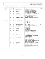
Table 21. Inverse Sinc Filter
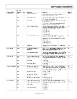
As shown in Table 20, the mixing functions of most of the
modes result in cross-coupling of samples between the I and Q
channels. The I and Q channels only operate independently
with the f
S
/2 mode. This means that real modulation using both
the I and Q DAC outputs can only be done in the f
S
/2 mode. All
other modulation modes require complex input data and
produce complex output signals.
Lower Coefficient
Upper Coefficient
Integer Value
H(1) H(9) +2
H(2) H(8) −4
H(3) H(7) +10
H(4) H(6) −35
H(5) N/A +401
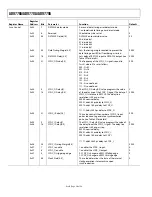
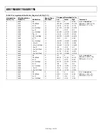
Table 20. Modulation Mixing Sequences
Modulation
The inverse sinc filter is disabled by default. It can be enabled by
setting the inverse sinc enable bit (Bit 3) in Register 0x02.
Mixing
Sequence
f
DAC
/2
I = I, −I, I, −I, …
0
–0.5
–1.0
–1.5
–2.0
–2.5
–3.0
–3.5
–4.0
–4.5
0
0.05 0.10 0.15
0.20 0.25 0.30 0.35
0.40
0.45 0.50
f/f
SAMPLE
(d
B
)
06
45
2-
08
8
SINC
–1
RESPONSE
COMBINED SINC AND SINC
–1
RESPONSE
Q = Q, −Q, Q, −Q, …
f
DAC
/4
I = I, Q, −I, −Q, …
Q = Q, −I, −Q, I, …
−f
DAC
/4
I = I, −Q, −I, Q, …
Q = Q, I, −Q, −I, …
f
DAC
/8
I = I, r(I + Q), Q, r(−I + Q), −I, −r(I + Q), −Q, r(I − Q),
…
Q = Q, r(Q − I), −I, −r(Q + I), −Q, r(−Q + I), I, r(Q + I),
…
where r = √2/2
INVERSE SINC FILTER
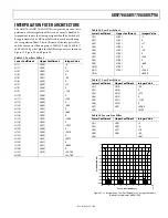
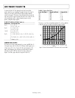
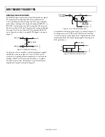
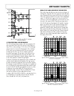
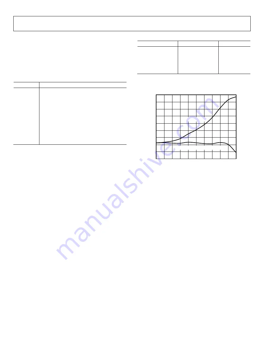
The inverse sinc filter is implemented as a nine-tap FIR filter. It
is designed to provide less than ±0.05 dB pass-band ripple up to
a frequency of 0.4 × f
DATA
. To provide the necessary gain at the
upper end of the pass band, the inverse sinc filter has an intrinsic
insertion loss of 3.4 dB. The transfer function is shown in
Figure 71 and the tap coefficients are given in Table 21.
Figure 71. Transfer Function of Inverse Sinc Filter with the DAC sin(x)/x Output

