PARALLEL MODE OPERATION:
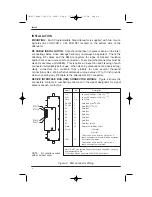
In the parallel mode of operation, the Smartstep attenuator accepts TTL-level
parallel data on the D0-D7 input data lines. Each data line controls a separate
attenuation cell, where a logic 1 input (TTL high) engages the attenuation cell, and
a logic 0 input (TTL low) bypasses the cell, providing a through path. The data
lines have a weak active pull-up to +5V, and therefore if the pin is left unconnect-
ed (or floating), will engage the attenuation cell. The on-board microcontroller
debounces the data lines and generates the proper timing and control sequence
for operation of the relays. The data line inputs are not latched, and must be driv-
en with a constant level to keep the desired attenuation setting.
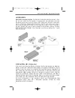
SERIAL MODE OPERATION:
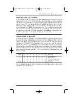
In the serial mode of operation, the Smartstep attenuator communicates over a
two-wire serial bus to the Weinschel Model 8210 Smartstep Interface. The bus
uses a clock (SCL) and data (SDA) line to send and receive programming and
configuration information. The messages sent over the bus use the software
protocol as defined in the ACCESS.bus™ V2.2 specification (Base Protocol) with
Weinschel-specific extensions to support the control of step attenuators (StepAttn
Protocol). These protocols and operating instructions can be located in the Model
8210 instruction manual (IM-288). The ACCESS.bus™ messages have the
following format:
Byte#
D7
D6
D5
D4
D3
D2
D1
D0
Description
1
D7
D6
D5
D4
D3
D2
D1
0
Destination address
2
S7
S6
S5
S4
S3
S2
S1
0
Source address
3
P
L6
L5
L4
L3
L2
L1
L0
Protocol flag & Msg Length
4
msg body- 0 to 127 bytes
4
X7
X6
X5
X4
X3
X2
X1
X0
Checksum
For an indepth discussion of the hardware and software operation, refer to the
ACCESS.bus™ specification.
5
3400T Series SmartStep™ Programmable Attenuators
IM-425 Model 3406T & 3408T-B.qxp 7/22/2006 2:38 PM Page 5

