Programmer’s Model
2-20
Copyright © ARM Limited 2000. All rights reserved.
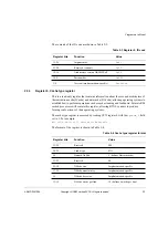
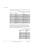
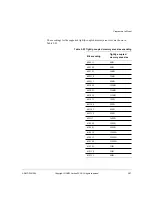
The instructions used to access the eight protection region/base size registers are listed
in Table 2-16.
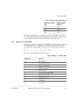
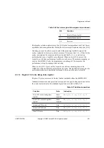
Each protection region/base size register has the format shown in Table 2-17.
You must align the region base to an area size boundary, where the area size is defined
in its respective protection region register. The behavior is unpredictable if this is not
done.
Table 2-16 Accessing protection region/base size registers
ARM instruction
Protection region/
base size register
MCR/MRC p15, 0, rd, c6, c7, 0
Memory region 7
MCR/MRC p15, 0, rd, c6, c6, 0
Memory region 6
MCR/MRC p15, 0, rd, c6, c5, 0
Memory region 5
MCR/MRC p15, 0, rd, c6, c4, 0
Memory region 4
MCR/MRC p15, 0, rd, c6, c3, 0
Memory region 3
MCR/MRC p15, 0, rd, c6, c2, 0
Memory region 2
MCR/MRC p15, 0, rd, c6, c1, 0
Memory region 1
MCR/MRC p15, 0, rd, c6, c0, 0
Memory region 0
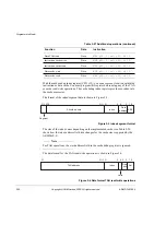
Table 2-17 Protection region/base size register format
Register bit
Function
31:12
Region base
5:1
Area size
0
1 = Region enable
0 = Region disable
Reset to 0.
Summary of Contents for ARM946E-S
Page 1: ...ARM DDI 0155A ARM946E S Technical Reference Manual ...
Page 6: ...vi Copyright ARM Limited 2000 All rights reserved ARM DDI 0155A 04 Limited Confidential ...
Page 54: ...Programmer s Model 2 34 Copyright ARM Limited 2000 All rights reserved ARM DDI 0155A ...
Page 70: ...Caches 3 16 Copyright ARM Limited 2000 All rights reserved ARM DDI 0155A ...
Page 78: ...Protection Unit 4 8 Copyright ARM Limited 2000 All rights reserved ARM DDI 0155A ...
Page 112: ...Coprocessor Interface 7 14 Copyright ARM Limited 2000 All rights reserved ARM DDI 0155A ...

