Functional Description
2-2
Copyright © 2002, 2003 ARM Limited. All rights reserved.
ARM DDI 0275D
2.1
Functional information
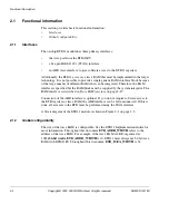
This section provides basic functional information:
•
•
2.1.1
Interfaces
The on-chip ETB11 module has three primary interfaces:
•
the trace port from the ETM11RV
•
a five-pin IEEE 1149.1 (JTAG) interface
•
an AHB slave interface to give software access to the ETB11 registers.
Additionally, the ETB11 accesses a trace RAM that must be implemented in the target
technology. It is not possible to provide a single generic RAM interface block because
of the large number of different RAMs that can be integrated. Therefore, the RAM
interface is specified but the RAM block must be supplied by the system integrator. The
RAM interface is described in
Connection of the AHB interface is optional. If you do not require software access to
the ETB registers or trace RAM, the AHB interface can be left unconnected. If this is
done, all accesses to the ETB must be performed using the JTAG interface.
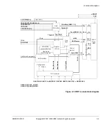
A block diagram of the ETB11 module is shown in Figure 2-1 on page 2-3.
2.1.2
Global configurability
The size of the trace RAM is configurable. See the ETB11 Implementation Guide for
more information. Throughout this document
ETB_ADDR_WIDTH
refers to the
address of the trace RAM. For example, if the trace RAM is 4KB, organized as
1024
x32-bit words, ETB_ADDR_WIDTH
is 10. ETB11 must always use 32-bit trace
RAM with ETM11RV. Throughout this document,
ETB_DATA_WIDTH
is 32.
Summary of Contents for ETB11
Page 6: ...List of Tables vi Copyright 2002 2003 ARM Limited All rights reserved ARM DDI 0275D ...
Page 8: ...List of Figures viii Copyright 2002 2003 ARM Limited All rights reserved ARM DDI 0275D ...
Page 46: ...Functional Description 2 26 Copyright 2002 2003 ARM Limited All rights reserved ARM DDI 0275D ...
Page 70: ...Signal Descriptions A 6 Copyright 2002 2003 ARM Limited All rights reserved ARM DDI 0275D ...
Page 78: ...Glossary Glossary 4 Copyright 2002 2003 ARM Limited All rights reserved ARM DDI 0275D ...


