20
Atmel AVR2052
8200M-AVR-11/11
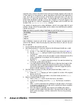
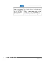
Table 8-3.
J3 jumper settings for all MeshBean types: serial/USB selection.
Jumper position
Description
J3 bridges central pin and RS-
232 pin
The board will use serial port (available in the
expansion slot) for connection to the host
J3 bridges central pin and USB
pin
The board will use USB for connection to the host
WARNING
Any other position for jumpers J2 and J3 or their omission may
permanently damage the MeshBean boards.
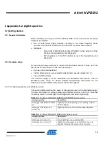
8.1.2.2 OTAU hardware setup
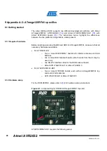
If you wish to demonstrate over-the-air upgrade functionality, an external flash
memory device supported by the Atmel BitCloud SDK and OTAU embedded
bootloader (for example, AT25F2048 or AT45DB041) must be attached to the Atmel
For details on OTAU demonstration, see Section
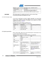
Table 8-4.
External flash and ZigBit/MCU pin assignment.
DataFlash
®
pin
ATZB-XX pin
Internal ATmega1281 MCU pin
MISO
USART0_RXD (38)
PE0
MOSI
USART0_TXD (39)
PE1
CLOCK
USART0_EXTCLK (40)
PE2
CS
ADC_INPUT3 (30)
PE3
8.1.3 System requirements
Before using the SDK, please ensure that the following system requirements are met
by your PC and development environment.
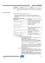
Table 8-5.
System requirements for ZigBit, ZigBit Amp, and ZigBit 900.
Parameter
Value
Note
CPU
Intel Pentium III, or higher,
800MHz
RAM
128MB
Free space on hard
disk
50MB
JTAG emulator
Atmel AVR JTAGICE mkII or
Atmel JTAGICE 3 emulator with
cable
Required to upload firmware onto
the boards and debug through
Operating system
Windows 2000/XP
IDE
Atmel AVR Studio 5 and
WinAVR 20100110
(1)
OR
IAR Embedded Workbench
AVR 5.51
(with IAR C/C++ Compiler for
AVR v5.51.0.50312
(1)
)
Required to upload firmware
images through JTAG (see
) and develop
applications using the API (see
Section
Java virtual machine Java Runtime Environment
(JRE) 6, or later
Required to run the WSNMonitor
application


