Atmel AVR2052
33
8200M-AVR-11/11
•
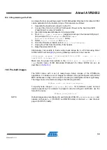
If at compile time the
CS_UID
parameter is set to 0, BitCloud attempts to load the
MAC address from the dedicated external EEPROM chip available on the
RCB128RFA1 as well as on the Atmel ATAVR128RFA1-EK1 board via the SPI
interface.
•
If there is no such chip present, then a zero MAC address will be assigned to the
device.
Note that for proper operation, all nodes in the network shall have unique MAC
address values. Hence, if an address cannot be obtained automatically from an
external source, separate firmware images shall be created for each device with a
unique
CS_UID
parameter specified in the application configuration.
9.2.3 Programming with Serial Bootloader
Programming using Serial Bootloader requires that the embedded bootloader code is
loaded to the device via JTAG. Firmware images for the embedded bootloader as
well as the Bootloader PC tool, which is needed to load the application image from a
PC to the device, are included in the Atmel Serial Bootloader software package
available for downloading from the Atmel website.
Images that shall be loaded to ATmega128RFA1 via JTAG may be found under the
\Embedded_Bootloader_images\Atmega128rfa1
directory in the package:
•
The
Bootloader_ATmega128RFA1_RCB_BB_RS232.hex
file for RCB128RFA1
•
The
Bootloader_ATmega128RFA1.hex
file for ATAVR128RFA1-EK1
In both cases, the fuse bits should be configured properly; namely, the
BOOTRST
fuse
should be enabled.
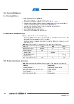
If the embedded bootloader is loaded, the following steps should be executed to
upload the application image file to the board:
1. Assemble the board and connect it to a PC:
a. For the ATRF4CE-EK:
a. Assemble the RCB128RFA1 and RCB breakout boards (RCB-
BB) together.
Connect the RS-232 interface cable to the J1 extender on the
RCB-BB and to the COM1 port on the PC.
b. For the Atmel ATAVR128RFA1-EK1:
b. Assemble the Atmel STK600 board and the ATAVR128RFA1-
EK1 card, as described in Section
c. Connect PC COM1 port to the RS-232 SPARE port on the
board. The RS-232 SPARE pins should be connected to the
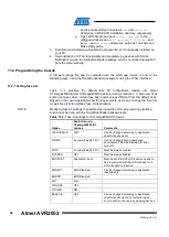
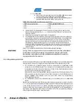
Table 9-5.
Host UART and MCU pin connections.
UART pin on host device
ATmega128RFA1 MCU pin
RXD
PD3
TXD
PD2
GND
D_GND
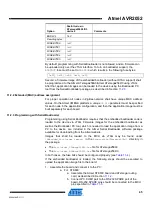
2. Install and run the Bootloader PC tool from the command line or use the GUI.
Specify the target image file in
.srec
format and the COM port, and launch the
firmware upload.
3. Reset the board using the reset button, if requested.
4. The Bootloader PC tool indicates the programming progress. Once an upload is
successfully completed, the board should restart automatically. If an upload fails,

