UMAX030440 Version 2B 12-51
12
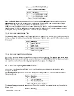
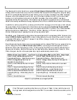
/, Result = InA divided by InB
13
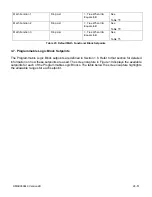
MIN, Result = Smallest of InA and InB
14
MAX, Result = Largest of InA and InB
Table 11: Math function X Operator Options
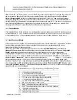
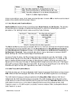
For logic operations (6, 7, and 8) scaled input greater than or equal to 1 is treated as TRUE. For
logic operations (0 to 8), the result of the function will always be 0 (FALSE) of 1 (TRUE). For the
arithmetic functions (9 to 14), it is recommended to scale the data such that the resulting operation
will not exceed full scale (0 to 100%) and saturate the output result.
When dividing, a zero divider will always result in a 100% output value for the associated function.
Lastly the resulting mathematical calculation, presented as a percentage value, can be scaled into
the appropriate physical units using the “
Math Output Minimum Range
” and “
Math Output
Maximum Range
” setpoints. These values are also used as the limits when the Math Function is
selected as the input source for another function block.
1.8. Programmable Logic Function Block
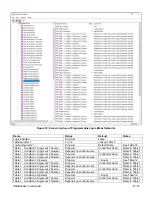
The Programmable Logic Function Block is a powerful tool. Programmable Logic can be linked to
up to three Lookup Tables, any of which would be selected only under given conditions. Thus, the
output of a Programmable Logic at any given time will be the output of the Lookup Table selected
by the defined logic. Therefore, up to three different responses to the same input, or three different
responses to different inputs, can become the input to another function block.
In order to enable any one of the Programmable Logic blocks, the “
Logic Enabled
” setpoint must
be set to ‘
True
’
. By default, all Logic blocks are disabled.
The three associated tables are selected by setting “
Table Number X
” setpoint to desired Lookup
Table number, for example selecting
1
would set Lookup Table 1 as TableX.
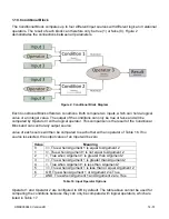
For each TableX there are three conditions that define the logic to select the associated Lookup
Table as Logic output. Each condition implements function
𝐴𝑟𝑔𝑢𝑚𝑒𝑛𝑡1 𝑂𝑝𝑒𝑟𝑎𝑡𝑜𝑟 𝐴𝑟𝑔𝑢𝑚𝑒𝑛𝑡2
where Operator is logical operator defined by setpoint “
Table X
– Condition Y Operator
”. Setpoint
options are listed in Table 12
. Condition arguments are selected with “
Table X
– Condition Y
Argument Z Source
” and “
Table X
– Condition Y Argument Z Number
” setpoints. If ‘
0
– Control
not Used
’ option is selected as “
Table x
– Condition Y Argument Z Source”
the argument is
interpreted as 0.
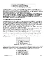
0
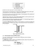
=, Equal
1
!=, Not Equal
2
>, Greater Than
3
>=, Greater Than or Equal
4
<, Less Than
5
<=, Less Than or Equal
Table 12: Table X
– Condition Y Operator Options
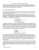
The three conditions are evaluated and if the result satisfies logical operation defined with “
Logical
Operator X
” setpoint, given in Table 13, the associated Lookup Table is selected as output of the
Logical block. Option ‘
0
– Default Table
’ selects associated Lookup Table in all conditions.
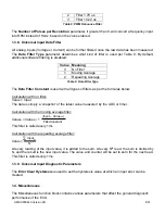
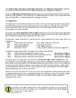
0
Default Table (Table1)
1
Cnd1 And Cnd2 And Cnd3
2
Cnd1 Or Cnd2 Or Cnd3
3
(Cnd1 And Cnd2) Or Cnd3
4
(Cnd1 Or Cnd2) And Cnd3


