X20 system modules • Counter modules • X20DC2395
X20 system User's Manual 3.10
829
4.11.14.12.9.3 Configure time measurement function for the rising edge
Name:
CfO_EdgeTimeRisingMode01 to CfO_EdgeTimeRisingMode04
These registers can be used to configure the time measurement function for the rising edge of the respective
channel.
Data type
Value
UINT
See bit structure.
Bit structure:
Bit
Description
Value
Information
0
Channel 1
...
0 - 3
Selects the channel for the starting edge
3
Channel 4
0
The falling edge of the channel configured in bits 0 to 3 serves
as the starting edge.
4
Selects the edge for the starting edge
1
The rising edge of the channel configured in bits 0 to 3 serves
as the starting edge.
5 - 6
Reserved
-
0
Triggered
1)
7
Trigger
1
Continuous
2)
8 - 11
Previous start edge
0 to 15
The value determines which entry in the starting edge FIFO
should be used to calculate the time difference.
0
8 Mhz
1
4 Mhz
2
2 Mhz
3
1 Mhz
4
500 kHz
5
250 kHz
6
125 kHz
12 - 15
Time measurement resolution
7
625 kHz
1)
2)
Time measurement runs continuously and is triggered at every edge.
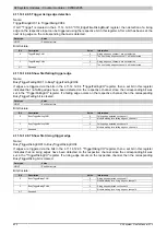
4.11.14.12.9.4 Trigger falling edge detection
Name:
TriggerFallingCH01 to TriggerFallingCH04
If bit 7 "Trigger" is cleared in the 4.11.14.12.9.2 "CfO_EdgeTimeFallingMode" register, then detection of a falling
edge on the respective input can be triggered using the respective bit in this register. After a bit has been set, the
next falling edge on the corresponding channel is detected.
Data type
Value
USINT
See bit structure.
Bit structure:
Bit
Description
Value
Information
0
Falling edges on channel 1 are not detected
0
TriggerFallingCH01
1
The next falling edge on channel 1 will be detected
...
...
0
Falling edges on channel 4 are not detected
3
TriggerFallingCH04
1
The next falling edge on channel 4 will be detected
4 - 7
Reserved
-
Summary of Contents for X20 System
Page 2: ......


