X20 system modules • Counter modules • X20DC4395
884
X20 system User's Manual 3.10
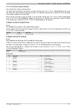
Configure SSI
Name:
CfO_SSI1cfg to CfO_SSI2cfg
This configuration register is used to set the coding, the clock rate and the number of bits. Default = 0. This must
be set once using an acyclic write command.
Data type
Value
UINT
See bit structure.
Bit structure:
Bit
Name
Value
Information
0 - 5
SSI value valid bits
x
00
1 MHz
01
500 kHz
10
250 kHz
6 - 7
Clock rate
11
125 kHz
8 - 13
SSI number of bits
x
Number of bits including leading zeros
14
Reserved
0
0
Binary coding
15
Keying
1
Gray coding
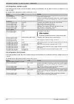
SSI advanced configuration
Name:
ConfigAdvanced01 to ConfigAdvanced02
This configuration register is used to set the coding, the clock rate, the number of bits and the monostable multivi-
brator settings. Default = 0. This must be set once using an acyclic write command.
It only differs from "CfO_SSI1cfg" by data length and additional monostable multivibrator testing.
Data type
Value
UDINT
See bit structure.
Bit structure:
Bit
Name
Value
Information
0 - 5
SSI value valid bits
x
00
1 MHz
01
500 kHz
10
250 kHz
6 - 7
Clock rate
11
125 kHz
8 - 13
SSI number of bits
x
Number of bits including leading zeros
14
Reserved
0
0
Binary coding
15
Keying
1
Gray coding
00
Check OFF, no additional clock bit
01
Check set to High level
10
Check set to Low level
16 - 17
Monostable multivibrator check
11
Level is clocked but ignored
18 - 31
Reserved
0
Enable SSI event function
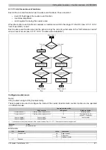
Name:
CfO_SSI1control to CfO_SSI2control
The two SSI encoder events can be enabled/disabled using this register.
Data type
Value
USINT
See bit structure.
Bit structure:
Bit
Description
Value
Information
0
Not sent
0
Event: SSI valid
1
Sent
0
Not sent
1
Event: SSI ready
1
Sent
2 - 7
Reserved
-
Summary of Contents for X20 System
Page 2: ......


