background image

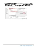
3. In the Available Sensors and Devices box, type MS-80 or locate the sensor in the Sensors >

Meteorological > Solar Radiation folder. Double-click the MS-80 (Pt100 temp) Secondary
Standard Pyranometer. Type the Sensitivity (uV/W/m^2) from calibration sheet. This value
is unique for each MS-80.

MS-80 Secondary Standard Pyranometer

2

Summary of Contents for MS-80

Page 1: ...Revision 11 2020 Copyright 2018 2020 Campbell Scientific Inc ...

Page 2: ...tions 5 4 Siting 5 5 Mounting procedure 6 6 MS 80 wiring 8 7 Solar radiation programming 9 8 Internal PT100 programming 10 9 Maintenance and troubleshooting 10 Appendix A Importing Short Cut code into CRBasic Editor 12 Appendix B MS 80 example program 13 Table of Contents i ...

Page 3: ...urer in the world enabling highest quality calibration compliant to international standards ISO IEC 17025 9847 For a similar pyranometer with RS 485 Modbus communications refer to the MS 80M www campbellsci com ms 80m l 2 QuickStart A video that describes data logger programming using Short Cut is available at www campbellsci com videos cr1000x datalogger getting started program part 3 Short Cut i...

Page 4: ...cate the sensor in the Sensors Meteorological Solar Radiation folder Double click the MS 80 Pt100 temp Secondary Standard Pyranometer Type the Sensitivity uV W m 2 from calibration sheet This value is unique for each MS 80 MS 80 Secondary Standard Pyranometer 2 ...
Page 5: ... be wired to the data logger and 3WHB10K a completion resistor such as the 3WHB10K is required to connect the MS 80 to a data logger Click OK after wiring the sensor 5 Repeat steps three and four for other sensors MS 80 Secondary Standard Pyranometer 3 ...

Page 6: ...inish and save the program Send the program to the data logger if the data logger is connected to the computer 9 If the sensor is connected to the data logger check the output of the sensor in the data logger support software data display in LoggerNet PC400 RTDAQ or PC200W to make sure it is making reasonable measurements MS 80 Secondary Standard Pyranometer 4 ...

Page 7: ...nce documents View at www campbellsci com ms 80 l 4 Siting The solar radiation sensor is usually installed horizontally but can also be installed at any angle including an inverted position Site the sensor to allow easy access for maintenance while ideally avoiding any obstructions or reflections above the plane of the sensing element It is important to mount the sensor such that a shadow or a ref...

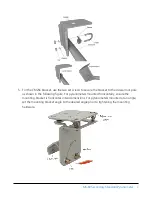
Page 8: ...ket 2 Secure the solar radiation sensor to the mounting bracket The blue dots in the following figure indicate the mounting holes used for this pyranometer 3 Using a diopter in combination with a solar compass install and orient the crossarm on the tripod or the mast If installing the mounting bracket on a vertical pole ensure the pole is truly vertical 4 Secure the mounting bracket to the crossar...

Page 9: ...shown in the following figure For pyranometers mounted horizontally ensure the mounting bracket is horizontal in two dimensions For pyranometers mounted at an angle set the mounting bracket angle to the desired angle prior to tightening the mounting hardware MS 80 Secondary Standard Pyranometer 7 ...

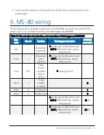
Page 10: ...WHB10K connection Red 1 Pyranometer signal high U configured for differential input1 DIFF H differential high analog voltage input Black 2 Pyranometer signal reference U configured for differential input1 DIFF L differential low analog voltage input Clear N C Shield tied to connector body of sensor analog ground White 3 PT100 voltage excitation H Green 4 PT100 signal L Yellow 5 PT100 ground U conf...

Page 11: ...e is not critical the autorange option can be used in the VoltDiff or VoltSE instruction the autorange adds a few milliseconds to the measurement time Otherwise select the input range as follows 1 Estimate the maximum expected input voltage by multiplying the maximum expected irradiance in W m 2 by the calibration factor in μV W m 2 Divide the answer by 1000 to give the maximum in millivolt units ...

Page 12: ... Vx1 1 2500 True 0 60 100 0 This assumes the 3WHB10K is connected to the SE3 SE4 and VX1 data logger terminals A typical PRT instruction is PRT Sensor_Temp 1 Rs 1 0 0 9 Maintenance and troubleshooting The MS 80 has no service items requiring scheduled replacement There is no accessible desiccant cartridge to maintain Use pure alcohol or distilled water and a lint free cloth to clean the dome remov...

Page 13: ...maged cables Ensure that the data logger program includes the correct parameters for the measurement instructions Check for the presence of strong sources of electromagnetic radiation and use the 50 or 60 Hz integration option in the data logger program if electromagnetic radiation can be a problem Check the cable for damage and ensure that it is properly connected to the data logger MS 80 Seconda...

Page 14: ...r additional refinement NOTE Once the file is edited with CRBasic Editor Short Cut can no longer be used to edit the program it created 2 To add the Short Cut wiring information into the new CRBasic program open the DEF file located in the C campbellsci SCWin folder and copy the wiring information which is at the beginning of the DEF file 3 Go into the CRBasic program and paste the wiring informat...

Page 15: ...mmed similarly Programming tips are provided at www campbellsci com videos datalogger programming Table B 1 Wiring for example program Wire color Function CR1000X connection 3WHB10K connection Red Pyranometer signal high 1H Black Pyranometer signal reference 1L Clear Shield analog ground White PT100 voltage excitation H Green PT100 signal L Yellow PT100 ground 2H HI pin 2L LO pin analog ground GND...

Page 16: ...Units IRR W m 2 Units Sensor_Temp DegC DataTable MS80 1 1 DataInterval 0 1 Min 10 Average 1 IRR IEEE4 False Average 1 Sensor_Temp FP2 False EndTable BeginProg Scan 1 Sec 3 0 Measure the irradiance VoltDiff IRR 1 mV200 1 True 3000 60 1000 SENS 0 Measure the PT100 PRT Temperature Sensor 3WHB10K BrHalf3W Rs 1 mV200 3 Vx1 1 2500 True 0 60 100 0 PRT Sensor_Temp 1 Rs 1 0 0 CallTable MS80 NextScan EndPro...

Page 17: ...Other manufacturer s products that are resold by Campbell Scientific are warranted only to the limits extended by the original manufacturer Refer to www campbellsci com terms warranty for more information CAMPBELL SCIENTIFIC EXPRESSLY DISCLAIMS AND EXCLUDES ANY IMPLIED WARRANTIES OF MERCHANTABILITY OR FITNESS FOR A PARTICULAR PURPOSE Campbell Scientific hereby disclaims to the fullest extent allow...

Page 18: ...tion or Repair Reference number contact your CAMPBELL SCIENTIFIC regional office Please write the issued number clearly on the outside of the shipping container and ship as directed For all returns the customer must provide a Statement of Product Cleanliness and Decontamination or Declaration of Hazardous Material and Decontamination form and comply with the requirements specified in it The form i...

Page 19: ...prohibit climbing by other persons Take reasonable precautions to secure tripod and tower sites from trespassers l Use only manufacturer recommended parts materials and tools Utility and Electrical l You can be killed or sustain serious bodily injury if the tripod tower or attachments you are installing constructing using or maintaining or a tool stake or anchor come in contact with overhead or un...

Page 20: ...info campbellsci fr www campbellsci fr Germany Location Phone Email Website Bremen Germany 49 0 421 460974 0 info campbellsci de www campbellsci de India Location Phone Email Website New Delhi DL India 91 11 46500481 482 info campbellsci in www campbellsci in South Africa Location Phone Email Website Stellenbosch South Africa 27 21 8809960 sales campbellsci co za www campbellsci co za Spain Locati...

Reviews: