TDR200-Based Time-Domain Reflectometry System
14
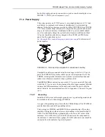
7.1.7.1 Determining Probe Constant, Kp, using PC-TDR
(p. 15)
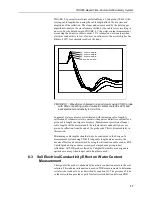
, presents the principles for TDR
measurements of soil electrical conductivity. The result of the measurement
must be multiplied by the probe constant (K
p
) to give bulk electrical
conductivity in S/m (Siemens/meter). The K
p
value can be measured using
PC-TDR
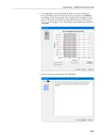
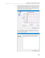
by following the instructions in the
Calibrate Probe
wizard
(p. B-1)
). The method requires
submersion of the TDR probe rods in deionized water of known temperature.
7.2 Programming
PC-TDR
software is used for system setup and troubleshooting. It displays
volumetric water content and electrical conductivity, switches multiplexer
channels, collects waveform and derivative data files, and determines probe
constant values needed for electrical conductivity measurements. It has a
Calibration Wizard that will automatically populate many of the sensor
settings.
PC-TDR
will also generate a CRBasic program.
The program generator wizard is accessible from the
File
menu and by clicking
. Additional editing of the program can be performed using the
CRBasic
Editor
. This is useful when there are devices and sensors added to the TDR
system that are not supported by
PC-TDR
program generator. CRBasic is
included in
PC400
or
LoggerNet
software.
The
TDR200()
CRBasic instruction is used to program the TDR200.
Programming basics are provided in the following sections. A complete
program example for a CRBasic data logger can be found in Appendix
(p. A-1)
.
If the data logger and
PC-TDR
are simultaneously measuring the
TDR200, an error will occur in either the data logger data stream
or
PC-TDR
. The error can be prevented by halting the data logger
program while controlling the TDR200 with
PC-TDR
. To halt the
CRBasic program, go to
File Control | Stop Program
. Make sure
to restart the data logger program after using
PC-TDR
.
7.2.1 TDR200() CRBasic Instruction
The
TDR200()
CRBasic instruction measures one TDR probe connected to the
TDR200 directly or multiple TDR probes connected to one or more SDM8X50
multiplexers.
TDR200
(Dest(), SDMAddress, Option, Mux/ProbeSelect, WaveAvg, Vp,
Points, CableLength, WindowLength, ProbeLength, ProbeOffset, Mult,
Offset, NoiseRejectionFreq, TDRFilterLevel, TDRLaa)
The
Vp
parameter needs to be 1 if using a soil moisture probe. If using a
coaxial sensor, the
Vp
parameter depends on the type of coaxial cable.
For the
NoiseRejectionFreq
parameter, choose 50 or 60 to eliminate 50 Hz or
60 Hz noise from AC lines (Section
(p. 19)
The
TDRFilterLevel
parameter can reduce noise of the TDR trace by applying
a weighted moving average to the data points (Section
NOTE

