PSoC Analog Coprocessor Pioneer Kit Guide, Doc. # 002-11190 Rev. *B
28
Kit Operation
3.1.2.4
Interfacing with an Inductive Proximity Sensor
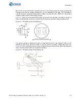
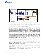
Inductive proximity sensing works on the principle of electromagnetic coupling between a sensor coil
and the metal disk to be detected. When the metal disk enters the electromagnetic field induced by a
sensor coil, some of the electromagnetic energy is transferred into the metal disk as shown in
. This transferred energy causes a circulating electrical current called eddy current. The
eddy current flowing in the metal disk induces a reverse electromagnetic field on the sensor coil,
which results in a reduction of effective inductance of the sensor coil.
The sensor coil is placed in parallel with a capacitor to form a tank oscillator circuit. The reduction in
the sensor coil inductance causes a shift in the resonant frequency of the tank oscillator circuit. This
shift in resonant frequency changes the amplitude of the signal across the sensor coil. The change in
the amplitude of the sensor coil signal is measured by the PSoC Analog Coprocessor to detect the
presence of the metal disk.
Figure 3-12. Field Coupling between Sensor and Metal
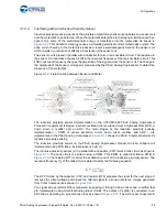
The inductive proximity sensor implementation on the CY8CKIT-048 PSoC Analog Coprocessor
Pioneer Kit consists of six stages: a sensor excitation circuit, a tank circuit, a high-pass filter (HPF), a
down mixer, a rectifier and an ADC. The main stages of the inductive proximity sensing
implementation – PWM of sensor excitation circuit, down mixer, rectifier, and ADC – are
implemented in the PSoC Analog Coprocessor.
shows the PSoC Creator schematic for
inductive proximity sensing.
The inductive proximity sensor on the PSoC Analog Coprocessor Pioneer Kit is an onboard coil
implemented using PCB trace; its inductance is 3 µH (L).
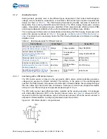
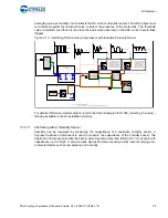
The inductive proximity sensor (L) in parallel with a capacitor (C80) forms a tank circuit as shown in
. The tank circuit is excited using a PWM. This PWM is called Excitation PWM in
. The resistor (R77) controls the excitation current of the inductive proximity sensor. The
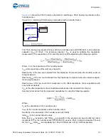
resonant frequency (f
r
) of the tank circuit is determined by the following equation.
The HPF formed by the capacitor (C57) and resistor (R78) prepares the signal for the next stage. It
removes the offset voltage and biases the filtered signal to a known reference voltage generated
from PVref Component as shown in
The signal across resistor R78 is measured by passing it through a down mixer and a rectifier that
are implemented using Universal Analog Block (UAB). The output of rectifier is connected to an
ADC that is operating on synchronous clock as shown in
. The ADC is set to operate in

