


ETK-S6.0 - User’s Guide
27
ETAS
Hardware Description
4.10.3
Triggering of Measurement Data Acquisition
Triggering of Measurement Data Acquisition (Configuration Type -A)
Parallel ETKs offer two or more trigger addresses that the ECU can write to for
signalling the validity of the specific raster data to the INCA system.
For serial ETKs this implementation is not feasible since this would require peri-
odic polling of the ECU memory by the ETK with all the associated drawbacks
(e.g. waste of debug interface bandwidth, time stamp accuracy, etc.).
The ETK-S6.0 uses a special register AUDMBR in the CPU hardware for signalling
measurement triggers. For Renesas SH2A generation microcontrollers this inter-
face is 16 bit wide, therefore, up to 16 dedicated hardware trigger signals can be
used with the ETK-S6.0.
Triggering of Measurement Data Acquisition (Configuration Type -B)
Parallel ETKs offer two or more trigger addresses that the ECU can write to for
signaling the validity of the specific raster data to the INCA system.
For this reason, serial ETKs use hardwired pins. Currently two to four data acqui-
sition interrupt lines (DAI1 to DAI4) are dedicated as hardware trigger signals.
The required circuitry for the trigger lines DAI1 to DAI4 on the ECU is shown in
Fig. 4-8 "Equivalent Circuitry of the ECU JTAG Interface (ECU)". The four hard-
ware triggers are active low signals.
4.10.4
Reset
The requirement for ETK reset mechanism is to ensure that power-up and
power-down behavior of ECU is clean and smooth. The ETK-S6.0 normally drives
/RES low during ECU power up or upon INCA request. The signal /RES of the
microprocessor is used by the ETK-S6.0 to detect when the ECU is in reset.
Item
Description
Agreements
t
1
Max. uncertainty of reset detec-
tion
t
1
< 200 ns
t
HOLD
Hold time of reset configuration
t
HOLD
~ 200 ns ... 400 ns
t
2
Reset delay of ETK for DAI startup
procedure
t
2
= 800 ns
t
3
First request for microntroller for
ETK detection;
Reading of DAI ports
t
3
>> 800 ns
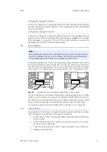
Note
The AUDATA[3..0] lines are also used for startup communication and general
data transfer between ETK and ECU, see Chapter 4.10.1 "Phases of the Startup
Protocol for AUD-II Operation".
Note
Interrupt lines DAI1 and DAI2 are also used for startup communication, see
Chapter 4.10.2 "Phases of the Startup Protocol for H-UDI Operation".


