303
CHAPTER 14 16-BIT RELOAD TIMER
14.3
Interrupt of 16-Bit Reload Timer
The interrupt of the 16-bit reload timer occurs when underflow of the counter is
detected. The underflow interrupt of counter can activate the DMA transfer and
extended intelligent I/O service (EI
2
OS).
■
Interrupt of 16-bit reload timer
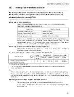
Table 14.3-1 shows the interrupt control bit and interrupt source of the 16-bit reload timer.
When the value of the TMR value is decremented from "0000" to "FFFF" during the 16-bit timer
register (TMR) count operation, an underflow occurs. When an underflow occurs, the timer
interrupt request flag (UF = 1) in the timer control status register (TMCSR) is set. When an
underflow interrupt is enabled (INTE = 1), an interrupt request is generated.
■
Interrupt of 16-bit reload timer, DMA transfer, and EI
2
OS
Table 14.3-2 shows the relationship between the interrupt source, interrupt vector, and interrupt
control register other than software interrupt.
■
Correspondence to DMA transfer and EI
2
OS function
The 16-bit reload timer corresponds to the DMA transfer function and EI
2
OS function.
To use DMA or EI
2
OS function, other interrupt that shares the interrupt control register (ICR)
must be disabled.
Table 14.3-1 Interrupt of 16-bit reload timer
Reload timer
Underflow interrupt
Timer interrupt request flag
TMCSR: UF (bit2)
Interrupt request output enable bit
TMCSR: INTE (bit3)
Interrupt generation source
Underflow of 16-bit reload timer
Table 14.3-2 Interrupt source, interrupt vector, and interrupt control register
Interrupt source
EI
2
OS
clear
μ
DMAC
channel
number
Interrupt vector
Interrupt control register
Number
Address
Number
Address
16-bit free-running timer overflow,
*
16-bit reload timer underflow
❍
12
#35
FFFF70
H
ICR12
0000BC
H
❍
: Interrupt request flag is cleared.
* : This interrupt source shares the interrupt source and interrupt number of other peripheral function. For
details, see Table 3.2-2.
Note:
If there are two interrupt sources in the same interrupt number, resource clears both interrupt request flags.
Therefore, when one of two sources uses the EI
2
OS/
μ
DMAC function, other interrupt function cannot use.
The interrupt request enable bit of the relevant resource is set to 0 to execute the software polling
processing.
Summary of Contents for MB90480 Series
Page 2: ......
Page 4: ......
Page 10: ...vi ...
Page 128: ...106 CHAPTER 4 RESET ...
Page 174: ...152 CHAPTER 6 LOW POWER CONSUMPTION MODE ...
Page 198: ...176 CHAPTER 7 MODE SETTING ...
Page 220: ...198 CHAPTER 9 TIMEBASE TIMER ...
Page 238: ...216 CHAPTER 11 WATCH TIMER ...
Page 280: ...258 CHAPTER 12 16 BIT INPUT OUTPUT TIMER ...
Page 406: ...384 CHAPTER 17 8 10 BIT A D CONVERTER ...
Page 478: ...456 CHAPTER 20 CHIP SELECTION FACILITY ...
Page 494: ...472 CHAPTER 21 ADDRESS MATCH DETECTION FUNCTION ...
Page 498: ...476 CHAPTER 22 ROM MIRROR FUNCTION SELECTION MODULE ...
Page 526: ...504 CHAPTER 23 2M 3M BIT FLASH MEMORY ...
Page 536: ...514 CHAPTER 24 EXAMPLES OF MB90F481B MB90F482B MB90F488B MB90F489B SERIAL PROGRAMMING ...
Page 570: ...548 CHAPTER 25 PWC TIMER ONLY MB90485 SERIES ...
Page 688: ......


