background image

e.bloxx Communication


COMMUNICATION


HB_EBLOXX_COM_E_V12.doc 

7


Gantner Instruments Test & Measurement GmbH


2.4.  Output Format 


The user can preset the format in which data shall be output via the bus with the 

Configuration Software ICP100.

 The  

modules adjust the data format accordingly and makes sure that data are available in the selected unit. 


For the transmission in the ASCII and PROFIBUS format the format settings listed in table 2.2 and 2.3 can be chosen. 
At the transmission in the MODBUS format the output format (integer or real) will automatically be confirmed (table 2.4). 
The coding of a real value in the MODBUS and PROFIBUS format is as follows: 


Coding of the real value: 


x =   s    ee...ee  mmm.....mmm 


Value: 

(-1)

· 2

e-127 

· 1,m   

# : <1> <- 8 -> <----- 23 -----> 


Format Settings 

Range of Values 

Unit 

dependent on sensor 

Field Length 

1 . . . . . . . . . . . . . . . . . . 8 

Decimals 

0 . . . field length-1 (max 6) 


Table 2.2    Format settings for transmission in the ASCII-format 


Format Settings 

Length 

Range of Values 

Bool 

1 byte 

(dec 0: FALSE)   and   (dec 255: TRUE) 

Integer 

2 byte 

(dec - 32768)    

  i  

     (dec +32767) 

Real 

4 byte 

(dec - 2

129


)      

   x   

   (dec + 2

129


SET 8 

1 byte 

(dec 0)            

   i   

      (dec 255


Table 2.3    Format settings for transmission in the PROFIBUS-format 


Format Settings 

Length 

Range of Values 

Integer 

2 byte 

(dec - 32768)    




i




  (dec +32767) 

Real 

4 byte 

(dec - 2

129


)    

   x   

≤ 

   (dec + 2

129


Table 2.4    Format settings for transmission in the MODBUS-format 


Example:

 The value 50.3094 cm shall be displayed. 


Summary of Contents for E Series

Page 1: ...e bloxx Communication Guide Vers No 12...

Page 2: ......

Page 3: ...y Any claims against the manufacturer based on the hardware or software products described in this manual shall depend exclusively on the conditions of the guarantee Any further reaching claims are ex...

Page 4: ...e bloxx Communication 2 HB_EBLOXX_COM_E_V12 doc Gantner Instruments Test Measurement GmbH...

Page 5: ...t the delivery is complete accessories documentation auxiliary devices etc 6 If the packaging has been damaged in transport or should you suspect that the product has been damaged or that it may have...

Page 6: ...suggestions for improvement you may confidently approach either your customer adviser or Gantner Instruments Test Measurement GmbH directly 14 However even if you just want to tell us that everything...

Page 7: ...ion Parameters 13 4 PROFIBUS PROTOCOL 15 4 1 Transmission Sequence 15 4 2 Diagnostic Data 16 4 3 Launching PROFIBUS DP Communication with a Hilscher Master 18 4 4 PROFIBUS DP Configuration for a Sieme...

Page 8: ...protocols are available within one download file The module itself recognizes the type of protocol for communication depending on the request from the host Therefore the protocol has not to be selecte...

Page 9: ...oding of a real value in the MODBUS and PROFIBUS format is as follows Coding of the real value x s ee ee mmm mmm Value 1 s 2 e 127 1 m 1 8 23 Format Settings Range of Values Unit dependent on sensor F...

Page 10: ...2 13 A6 5030 42 49 3C D3 50 3094 3 xx xx 50309 42 49 3C D3 50 3094 4 xx xx 503094 42 49 3C D3 50 3094 5 xx xx 5030940 42 49 3C D3 50 3094 6 xx xx 50309400 42 49 3C D3 50 3094 Table 2 6 Output formats...

Page 11: ...earing values for T1 T2 and T3 and the adjustment range in the following table 3 1 Protocol Baud rate T1min T1max T2min T2max T3min T3max adjustable no no yes no no yes A S C I I 19 200 bps 38 400 bps...

Page 12: ...2 Characters Positive Acknowledge Negative Acknowledge 1 Character 1 Character SD Start Delimiter Length 1 byte The Start Delimiter SD marks the beginning of a telegram In an ASCII protocol it has th...

Page 13: ...ted in the ASCII protocol from Start Delimiter SD Destination Adress DA and Data Unit CheckSum_ASCII SD DA DataUnit mod 256 In the ASCII protocol the value is indicated as a two digit ASCII string ASC...

Page 14: ...ariable with aa W kk d d cc cr ACK NAK without aa W kk d d cr ACK NAK Table 3 3 Instruction set in ASCII protocol Char Meaning Length Range start delimiter for request telegram with check sum 1 ASCII...

Page 15: ...7 M6 M5 M4 M3 M2 M1 hex XY X Y ASCII XY If the bit Kn in the variable status is set it indicates that an error has occurred in variable n A variable error is given when the measuring value is outside...

Page 16: ...og Input Variable AI 5 Setpoint Variable SP ASCII 2 Arithmetic Variable AR 6 Alarm Variable AL ASCII 3 Digital Output Variable DO 9 Controller Variable CO Coding data format ASCII 0 no format ASCII 1...

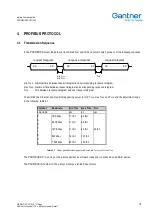
Page 17: ...elegram TSYN time between response telegram and next request telegram You will find the minimum and maximum appearing values for min TSDR max TSDR and TSYN and the adjustment range in the following ta...

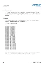
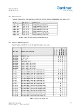
Page 18: ...Modbus Error 1 Unit_Diag_Bit 1 Modbus Error 2 Unit_Diag_Bit 2 Modbus Error 3 Unit_Diag_Bit 3 Modbus Error 4 Unit_Diag_Bit 4 Modbus Error 5 Unit_Diag_Bit 5 Modbus Error 6 Unit_Diag_Bit 6 Modbus Error...

Page 19: ...Module Error 6 Currently not defined reserved Module Error 7 Currently not defined reserved Module Error 8 Currently not defined reserved Error Var 1 Error for variable 1 sensor break linearisation e...

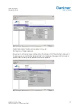
Page 20: ...located in the GSD directory in the installation directory of ICP 100 or directly received from the Gantner Instruments Test Measurement GMBH has to be copied to the directory Fieldbus Profibus GSD i...

Page 21: ...dress in the system Min Slave Interval Needed update rate Now you have to set the correct process interface settings Therefore open the DP Master Settings window and in this window you have to mark Bu...

Page 22: ...ut and set the address of this slave For the configuration of PROFIBUS DP variables information is read from the GSD File The variable settings will be displayed in the list field 1 in the window Slav...

Page 23: ...then press those buttons to add them to the field 2 The order of the variables has to be the same as in the Configuration Table from top to bottom If you click with the right mouse button on the field...

Page 24: ...e bloxx Communication PROFIBUS PROTOCOL 22 HB_EBLOXX_COM_E_V12 doc Gantner Instruments Test Measurement GmbH...

Page 25: ...modules are connected to this station via PROFIBUS DP Each e bloxx module is then configured separately according to their variable settings in the Configuration Software ICP 100 In order to set up a...

Page 26: ...try Hardware in the right field A window for the hardware configuration will be opened Open the directory SIMATIC 300 in the list field on the right side of this windows Then go to the sub directory R...

Page 27: ...rement GmbH Now you see the Profile Rail Element in the main window On the right list field open the directory SIMATIC 300 Then open the sub directory PS 300 There you find the entry PS 307 2A for the...

Page 28: ...herefore open the directory SIMATIC 300 and drag the corresponding controller into the second line of the Profile Rail Element When the SPS controller is dropped into the second line of the Profile Ra...

Page 29: ...on Bus Parameters The following window will be opened Here you see the timing settings of the PROFIBUS DP interface Note The option activate cyclic distribution of pus parameters must not be activated...

Page 30: ...the PROFIBUS DP line in the main window Therefore open the directory PROFIBUS DP on the right side of the window In the sub directories Further Fieldbus Devices I O click on e bloxx and drag that ent...

Page 31: ...e bloxx There you see the different possible configuration values 1 The values must be assigned to the correct slots in the table 2 at the bottom of the main window Therefore drag the corresponding co...

Page 32: ...n the SIMATIC Master If you click with the right mouse button on the field DP Real Cfg of a variable in the Configuration Table the following window will open Here you can see the DP settings in detai...

Page 33: ...H Now select the Components level Copy the Component OB1 eight times The components are necessary for the SPS to communicate via PROFIBUS DP The copies must have the names OB80 OB81 OB82 OB85 OB86 OB8...

Page 34: ...the minimum and maximum appearing values for T1 T2 and T3 and the adjustment range in the following table 2 14 protocol baud rate T1min T1max T2min T2max T3min T3max adjustable no no yes no no yes M O...

Page 35: ...pectively At the end the telegrams contain a check sum CRC with the length of 16 bits The check sum is calculated from the whole telegram without the CRC itself The CRC polynomial is u 15 u 13 1 The s...

Page 36: ...can be read Request Telegram Response Telegram ADR ISM address hex 00 7F FNR Function number hex 03 REGSTA Address of the first register to be read REGNUM Number of registers to be read BYTNUM Number...

Page 37: ...be read Request Telegram Response Telegram ADR ISM address hex 00 7F FNR Function number hex 04 REGSTA Address of the first register to be read REGNUM Number of registers to be read BYTNUM Number of...

Page 38: ...single register can be written Request Telegram Response Telegram ADR ISM address hex 00 7F FNR Function number hex 06 REGADR Address of the register to be written DATA Data word hex 0000 FFFF CRC Ch...

Page 39: ...elegram has been received in correct form the module will send this telegram back unchanged echo telegram Request Telegram Response Telegram ADR ISM address hex 00 7F FNR Function number hex 08 SUBFCT...

Page 40: ...st Telegram Response Telegram ADR ISM address hex 00 7F FNR Function number hex 10 REGSTA Address of the first register to be written REGNUM Number of registers to be written BYTNUM Number of databyte...

Page 41: ...gh word 0 65535 002F ro rw variable 16 real value low word 0 65535 Only e bloxx A6 2CF which has 16 variables Attention The low word and the high word of a variable always have to be read or written s...

Page 42: ...ariable 8 1100 111F variable information for variable 9 1120 113F variable information for variable 10 1140 115F variable information for variable 11 1160 117F variable information for variable 12 118...

Page 43: ...n counter Digital Output hex 0 no hex 1 host output hex 2 PWM output hex 3 process output Coding tare reset hex 0 no tare reset hex 1 tare reset valid Device Information Register Type Content Length 0...

Page 44: ...K12 K9 K8 K5 K4 K1 hex 0XYZ 0 X Y Z ASCII 0XYZ If the bit Mn in the module status is set it indicates that an error has occurred in the sensor module Valid is M1 1 EEPROM Error M2 1 FLASH Error M3 1...

Page 45: ...nsmission Order The transmission order is MS Byte for LSB Byte with LS Bit for MS Bit 6 4 Primary Build Up Of The Frame 6 4 1 Request Frame SYNC2 Start delimiter for addressed communication 0xA6 CHAR...

Page 46: ...0xC6 CHAR ADDR Address of the slave 0x01 0x7F CHAR L Length of the flowing Data L ErrorCode CHAR L 0x01 0xFF ERROR CODE Error code of the responding slave CHAR 0x01 Command not available 0x02 Invalid...

Page 47: ...n time maximum answer delay the master must recognize it and start a user defined error procedure An incorrect command e g command not available for the slave will be answered with an NAK 6 8 Command...

Page 48: ...ponse Telegrams Acknowledge L Length of the data min 0x02 CHAR DiagData Diagnostic data CHAR STRING DiagData 0 Module State MSB DiagData 1 Module State LSB DiagData 3 Variable State 15 8 DiagData 4 Va...

Page 49: ...the data 0x01 0xFF CHAR VALUE 0 Values 0 to be transmitted BOOLEAN INTEGER LONGINTEGER FLOAT VALUE n Values n to be transmitted BOOLEAN INTEGER FLOAT n depends on the e bloxx equipment e bloxx A1 x m...

Page 50: ...xx A1 x max n 0x07 e bloxx A4 x max n 0x07 e bloxx A5 1 max n 0x07 e bloxx A6 2CF max n 0x0F e bloxx A9 1 max n 0x07 e bloxx D1 x max n 0x07 FCS Frame check sequence of the request CHAR Response Teleg...

Page 51: ...and 12 Set Single Variable 0x0C CHAR VarIndex Variable number to be set 0x00 n CHAR e bloxx A1 x max n 0x07 e bloxx A4 x max n 0x07 e bloxx A5 1 max n 0x07 e bloxx A6 2CF max n 0x0F e bloxx A9 1 max n...

Page 52: ...DOR The vendor of the slave e g Gantner CHAR STRING L2 Length of the device type string max 0x14 CHAR DEVTYPE The type of the device e g e bloxx A1 1 CHAR STRING L3 Length of the hardware release stri...

Page 53: ...xx D1 x max n 0x07 SelIndex Selection index for the special values CHAR SelIndex_NetValue 0 SelIndex_TareValue 1 SelIndex_GrossValue 2 SelIndex_ZeroValue 3 SelIndex_UnbalancedVaule 4 Meaning of the va...

Page 54: ...riable number to be set 0x00 n CHAR e bloxx A1 x max n 0x07 e bloxx A4 x max n 0x07 e bloxx A5 1 max n 0x07 e bloxx A6 2CF max n 0x0F e bloxx A9 1 max n 0x07 e bloxx D1 x max n 0x07 SelIndex Selection...

Page 55: ...Notice Information in this manual are valid from June 17 th 2005 until revocation Further changes and completion of the manual are reserved and possible without notice...

Page 56: ...Gantner Instruments Test Measurement GMBH Montafonerstra e 8 A 6780 Schruns Austria Tel 43 0 5556 73784 410 Fax 43 0 5556 73784 419 E Mail office gantner instruments com www gantner instruments com...

Reviews: