background image

OC-G-5646-2-ET OLED Lighting Controllers - User Manual

10

Command configuration

The OC-G-5646-2-ET can be configur ed thr ough the Ether net

connection using UDP or TCP/IP. You can download sam ple C++, C#,

VB.NET code fr om

www.gardasoft.com

to allow configur ation.

10.1

Ethernet configuration

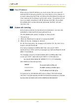
For TCP, com m ands fr om a host should be sent to destination por t

30313 with r eplies sent to destination por t 30312. For UDP, com m ands

fr om a host should be sent fr om sour ce por t 30312 to destination por t

30313. Replies ar e sent fr om sour ce por t 30313 to destination por t

30312.

A car r iage r etur n (ASCII 13) char acter should be sent to ter m inate the

com m and line, in case m ultiple packets get joined together .

10.2

Command structure

Com m unication consists of com m ands sent by the host (contr olling

PC). All output gener ated by the com m and is r etur ned in r eply UDP or

TCP/IP packets. The last char acter sent is

>

(‘gr eater than’ sym bol).

Once this is r eceived, the host knows that the com m and has been

com pleted.

We r ecom m end that the host waits for the > sym bol befor e sending

the next com m and. UDP com m unications ar e not guar anteed to ar r ive,

so the host softwar e m ust be able to cope with lost m essages.

Using the

GT

com m and, a host can r equest that a m essage is sent to it

whenever an er r or occur s.

Sever al com m ands can be put into one com m and line by separ ating

them by a sem i-colon ( 

;

).The OC-G-5646-2-ET sends any r eplies to the

com m ands followed by a

>

char acter to show that the com m and line

has com pleted.

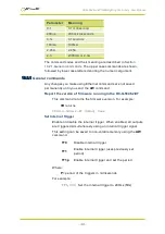
All com m ands com pr ise a code of two letter s followed by any optional

par am eter s. All spaces in the com m ands ar e ignor ed.

Num er ic par am eter s ar e separ ated by a com m a ( 

,

). For a par am eter

which is a tim e per iod, the default units ar e m illiseconds. ‘s’, ‘m s’ or ‘us’

can be added to the end of the num ber to indicate seconds,

m illiseconds or m icr oseconds. For cur r ents, ‘A’ or ‘m a’ can be added to

indicate am ps or m illiam ps. The default unit is am ps.

Not e:

par am eter s ar e in ‘USA/UK’ for m at so that a half is wr itten ‘0.5’

not ‘0,5’. For exam ple:

29

Summary of Contents for OC-G-5646-2-ET

Page 1: ...OC G 5646 2 ET OLED Lighting Controllers Issue 003 User manual www gardasoft com...

Page 2: ...r their application The user must ensure that incorrect functioning of this equipment cannot cause any dangerous situation or significant financial loss to occur Deliberate acts of endangerment and va...

Page 3: ...1 Environmental considerations 15 6 Connections 17 6 1 Power supply 17 6 2 Lighting output 18 6 3 Trigger inputs 18 6 4 Ethernet connection 18 6 5 Connectors 19 7 General description 20 7 1 Light auto...

Page 4: ...ng Controllers User Manual 10 2 2 Lighting channel commands 33 10 2 3 Command summary 35 11 Reference information 36 11 1 Specification 36 11 2 Restrictions 37 11 3 Error codes 38 11 4 Fatal error cod...

Page 5: ...tion 5 Mounting the OC G 5646 2 ET and connect the OC G 5646 2 ET up to a power supply as described in Section 6 Connections Set up the OC G 5646 2 ET for the desired operation as described in the con...

Page 6: ...o cause a burn if touched Place in a position where personnel cannot accidentally touch it and ensure there is a free flow of air around the unit 2 2 Electrical The OC G 5646 2 ET produces high energy...

Page 7: ...insulated by an appropriately rated heat resistant sleeve or prevented from touching the metal enclosure of the controller or its heatsink where fitted Power supply cabling to the controller must be r...

Page 8: ...vided by the equipment may be impaired 2 4 Installation guidance disclaimer This information is for guidance only Installers must perform their own risk assessment specific to each installation While...

Page 9: ...ass Sie die Grenzwerte f r das Ger t nicht berschreiten siehe Section 11 Reference information Bei den maximalen Grenzwerten kann das Geh use des OC G 5646 2 ET 65 C berschreiten was ausreichend ist u...

Page 10: ...zugelassen sein Das Netzger t kann auch nach gleichwertigen oder h heren Standards zugelassen sein Alle stromf hrenden Leiter die vom Stromnetz abgeleitet sind m ssen ebenfalls Sicherheitskleinspannun...

Page 11: ...gemein Das OC G 5646 2 ET darf nicht in Anwendungen eingesetzt werden bei denen es durch einen Ausfall des Ger ts zu einer Gefahr f r die Gesundheit von Personen oder zur Besch digung anderer Ger te k...

Page 12: ...11 Reference information Lorsqu il atteint ses valeurs nominales maximales le boitier OC G 5646 2 ET peut d passer les 65 C ce qui est suffisant pour provoquer des br lures en cas de contact Placez l...

Page 13: ...ion secteur doivent aussi poss der une sortie tension de s curit extra basse Se reporter la Section 11 Reference information pour les limites de tension autoris es Lorsqu il atteint ses valeurs nomina...

Page 14: ...ersonnes et l int grit des quipements seraient mises en danger s il venait tomber en panne Si l quipement est utilis autrement qu aux fins pr vues par le fabricant la protection offerte par l quipemen...

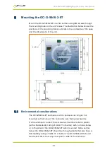
Page 15: ...onsiderations The OC G 5646 2 ET enclosure is a fire enclosure as long as it is mounted so that none of the connectors are facing downwards If a fire enclosure is used the enclosure should be metal or...

Page 16: ...L x IPS Where VPS Power supply voltage VL Rated voltage for lighting IPS Maximum current delivered by the power supply Either limit the power supply output current so that not more than 30W can be dis...

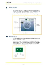
Page 17: ...nnectors See Section 11 Reference information for information about connection ratings 6 1 Power supply Any power supply derived from mains electricity must have a Safety Extra Low Voltage SELV output...

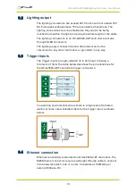
Page 18: ...a lines must not be commoned to any other controllers or grounded in any way 6 3 Trigger inputs The trigger inputs are opto isolated 3V to 24V input drawing a minimum of 3mA The table below describes...

Page 19: ...be required these can be obtained from W rth www we online com Farnell www farnell com or Newark www newark com See the table below for further information Connector Description W rth part number Far...

Page 20: ...uration and the brightness can be set Switched In switched mode a trigger input is used to switch the output current on and off The output is only enabled when the trigger input has a voltage on it 7...

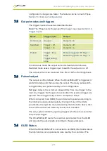
Page 21: ...n the OC G 5646 2 ET is triggered it waits for a delay and then pulses the output The delay pulse width retrigger delay and pulse intensity are all configurable Retrigger delay is the minimum allowed...

Page 22: ...ncel the error see Section 10 Command configuration The OC G 5646 2 ET controller re senses the light Error Reason 34 37 Internal power dissipation is too high Output turned off 35 43 Output current t...

Page 23: ...ly connected to a network switch hub or router but you can connect it directly into the network port on a PC using a crossover cable 8 2 IP Address The OC G 5646 2 ET needs an IP address to communicat...

Page 24: ...uration 8 2 1 DHCP Most networks use a DHCP server If there is a PC on the network you may be able to find out whether a PC on the same network uses DCHP as follows i Right click the Windows 10 icon a...

Page 25: ...ts i On power up ii When an IP address is received or renewed by DHCP iii When an enquiry message is received On the first two events the message is broadcast On the third it is a reply to a single IP...

Page 26: ...er s IP address displayed in GardasoftMaint into your web browser which will display the Main screen GardasoftMaint software is available from www gardasoft com Downloads 9 1 Main page The main page s...

Page 27: ...ameters for each output channel Pressing the Submit button updates the OC G 5646 2 ET configuration and saves the changes to non volatile memory On this page you can Change the current rating for the...

Page 28: ...when the OLED nears the end of its life and again when the OLED reaches the end of its life 9 3 General setup page The General Setup page allows you to set up or clear the webpage s password and set...

Page 29: ...an symbol Once this is received the host knows that the command has been completed We recommend that the host waits for the symbol before sending the next command UDP communications are not guaranteed...

Page 30: ...ly until you send the AW command Report the version of firmware running in the OC G 5646 2 ET This command returns the firmware version For example VR returns VROC G 5646 2 ET HWnn Vxxx Set Internal T...

Page 31: ...ow Configuration ST This command shows the operational parameters for all channels in the controller A typical output for an OC G 5646 2 ET controller is CH1 MD0 S50 0 0 0 DL1 000ms PU1 000ms RT0 0us...

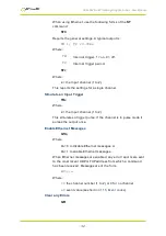
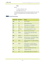
Page 32: ...e an Input Trigger TRc Where c the input channel 1 to 2 This simulates a trigger pulse If the channel is in pulse mode it pulses the output once Enable Ethernet Messages GTm Where m 0 to disable Ether...

Page 33: ...its own then the password is cleared There are six optional parameters which are decimal ASCII values for a password from one to six letters A value of 65 is A 66 is B and so on to 90 is Z You can se...

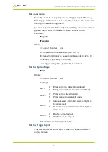
Page 34: ...y from trigger to pulse in milliseconds 0 02 to 10 s setting in percent s 0 to 500 r retrigger delay This parameter is optional Set the Option Flags REc m Where c output channel 1 to 2 m flags bit 1 0...

Page 35: ...Ethernet messages GR GR Clear any error conditions EY EY65 66 Set webpage password to AB VR VR Read the firmware version RS RS2 65 Set channel 2 to 65 brightness continuous RW RW1 50 Set channel 1 to...

Page 36: ...rent per channel Maximum 10A Pulse Maximum 10A Switched Maximum 2A Continuous Maximum output voltage 72V Max output voltage to OLED 46V Output power 30W per channel maximum Trigger input 2 trigger inp...

Page 37: ...t being turned on or off is 10 s The maximum output current is 10A per channel Pulse Mode The maximum output current is 10A per channel For high current pulses the following limits apply Pulse current...

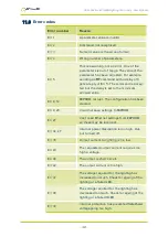
Page 38: ...pt The configuration has been cleared Err 9 20 Could not save settings to EEPROM Err 27 Can t read Ethernet settings from EEPROM so these may be incorrect Err 34 47 Internal power dissipation is too h...

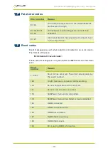
Page 39: ...an error occurs The format of these is Evt channel event code These event messages are only sent after the GT1 command has been sent Event number Reason 1 to 127 An error has occurred The error code...

Page 40: ...OC G 5646 2 ETOLED Lighting Controllers User Manual These pages are left blank for your notes 40...

Page 41: ...OC G 5646 2 ETOLED Lighting Controllers User Manual 41...

Page 42: ...sion 003 January 2020 Copyright 2020 Gardasoft Vision Ltd Gardasoft Vision Ltd Trinity Court Buckingway Business Park Cambridge CB24 4UQ UK tel 44 1954 234970 Gardasoft LLC Oak Ridge Road Weare New Ha...

Reviews: