background image

BAROsense 

-   13   -


V1.2


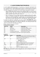
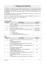
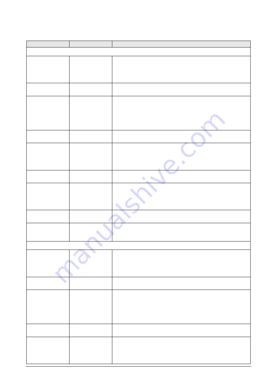
Analog output: 

Command 

Reply


Description 


Current output 

CAOn 

&| 

Enable/disable the offset of the current analog output: 


Offset disabled if n=0 (0…20 mA) 


Offset enabled if n=1 (4…20 mA) 

Default 

: Offset enabled (n=1) 

RAO 

& n| 

Reads the setting of the offset for the current analog 
output. 

CASOn 

&| 

Sets the direct or reversed correspondence between cur-
rent analog output and pressure: 


Min. mA 

 Min. press., Max. mA 

 Max. press. if n=0 


Min. mA 

 Max. press., Max. mA 

 Min. press. if n=1 

Default 

: Direct correspondence (n=0) 

RASO 

& n| 

Reads the type of correspondence (direct or reversed) 
between current analog output and pressure. 

CALn 

&| 

Sets n as the minimum pressure value for the current 
analog output. 

For the value n to be entered, see 

Note 1

 below. 

Default 

: 60000 (=600.00 hPa) 

RAL 

& n| 

Reads the minimum pressure value for the current analog 
output (see 

Note 1

 below). 

CAHn 

&| 

Sets n as the maximum pressure value for the current 
analog output. 

For the value n to be entered, see 

Note 1

 below. 

Default 

: 110000 (=1100.00 hPa) 

RAH 

& n| 

Reads the maximum pressure value for the current ana-
log output (see 

Note 1

 below). 

RAF 

& 0


Minimum value 
Maximum value


Simultaneously provides the information obtainable with 
the RAL e RAH commands. 

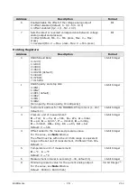
Voltage output


CVOn 

&| 

Enable/disable the offset of the voltage analog output: 


Offset disabled if n=0 (0…1/0…5/0…10 V) 


Offset enabled if n=1 (0,2…1/1…5/2…10 V) 

Default 

: Offset disabled (n=0) 

RVO 

& n| 

Reads the setting of the offset for the voltage analog 
output. 

CVSOn 

&| 

Sets the direct or reversed correspondence between volt-
age analog output and pressure: 


Min. V 

 Min. press., Max. V 

 Max. press. if n=0 


Min. V 

 Max. press., Max. V 

 Min. press. if n=1 

Default 

: Direct correspondence (n=0) 

RVSO 

& n| 

Reads the type of correspondence (direct or reversed) 
between voltage analog output and pressure. 

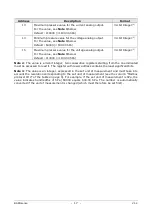
CVLn 

&| 

Sets n as the minimum pressure value for the voltage 
analog output. 

For the value n to be entered, see 

Note 1

 below. 

Default 

: 60000 (=600.00 hPa) 

Summary of Contents for DeltaOHM BAROsense

Page 1: ...Operating manual Barometric transmitter BAROsense www deltaohm com English Keep for future reference ...

Page 2: ...ENTS 1 INTRODUCTION 3 2 TECHNICAL SPECIFICATIONS 4 3 INSTALLATION 6 3 1 ELECTRICAL CONNECTIONS 7 4 CONFIGURATION AND MEASUREMENT 9 5 ASCII PROPRIETARY PROTOCOL 10 6 MODBUS RTU PROTOCOL 15 7 SAFETY INSTRUCTIONS 18 8 ORDERING CODES 19 ...

Page 3: ...can be supplied with an additional analog output which can be selected by the user in current or voltage via an internal jumper The current output is user configurable 0 20 mA or 4 20 mA default while the voltage output must be defined when ordering 0 1 V 0 5 V or 0 10 V The transmitter digital output enables the transmission of the measurements over long distances and connects the transmitter to ...

Page 4: ...Sensor PTAT integrated in humidity module Measuring range 40 105 C Resolution 0 1 C Accuracy 0 2 C in the range 0 60 C 0 2 0 05 T C in the range T 40 0 C 0 2 0 032 T 60 C in the range T 60 105 C Long term stability 0 05 C year General specifications Output RS485 with Modbus RTU or ASCII proprietary protocol Optional analog output selectable in current 0 4 20 mA or volt age 0 1 V 0 5 V or 0 10 V de...

Page 5: ... available for the pressure measurement with different resolution IR 0 32 bit and IR 2 16 bit With the ASCII proprietary protocol the resolution is unique Resolution Unit of measurement ASCII proprietary protocol Modbus protocol IR 0 32 bit Display Modbus protocol IR 2 16 bit Pa 1 Pa 10 Pa hPa 0 01 hPa 0 1 hPa kPa 0 001 kPa 0 01 kPa mbar 0 01 mbar 0 1 mbar bar 0 00001 bar 0 0001 bar atm 0 00001 at...

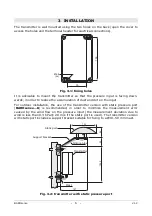
Page 6: ...t and dirt on the input For outdoor installation the use of the transmitter version with static pressure port BAROsense K is recommended in order to minimize the measurement error caused by the wind flow on the pressure input the measurement deviation due to wind is less than 0 3 hPa 20 m s if the static port is used The transmitter version with static port includes a support bracket suitable for ...

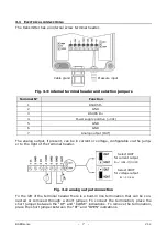
Page 7: ...age configurable via the jump er to the right of the terminal header Fig 3 4 analog output connection To the left of the terminal header there is a built in line termination that can be con nected or removed through a short jumper To connect the termination place the short jumper between the RT and CLOSE indications To remove the termination place the short jumper between the RT and OPEN indicatio...

Page 8: ...D D GND 220Ω 220Ω Shield Shield Lmax 1200m D D D 1 2 3 4 GND D VDC 5 GND D D Fig 3 5 RS485 connection Other sensors with RS485 output Termination Termination PLC data logger or RS485 USB or RS485 RS232 converter for PC ...

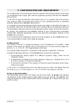
Page 9: ...ribed in detail in the following chapters Analog output The output is current or voltage depending on the configuration of the IOUT VOUT jumper on the board By default the current output is 4 20 mA and the voltage out put is 0 1 0 5 V or 0 10 V depending on the model The analog output is preset to correspond to the pressure range 600 1100 hPa Using the proprietary protocol or the MODBUS RTU protoc...

Page 10: ...ial command CAL USER ON must be sent first the instrument replies with USER CAL MODE ON The command CAL USER ON is automatically disabled after a few minutes of inactivity If the settings should be only read the command CAL USER ON is not required Below is the list of the serial commands Instrument information Command Reply Description G0 Model Instrument model G1 Revision Instrument hardware revi...

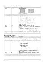
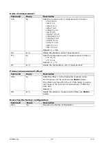
Page 11: ...protocol Immediate reception if n 0 violates protocol Waiting 3 5 characters if n 1 respects protocol Default Immediate reception n 0 RMW n Reads the setting of waiting time after transmission with MODBUS RTU protocol Measurements reading Command Reply Description S0 Disables the sending of the measurements enabled with S1 S1 Enables the sending of the measurements at regular inter vals To set the...

Page 12: ...ure unit of measurement of index n C if n 0 F if n 1 Default 0 C HT n Reads the temperature unit of measurement Pressure measurement offset Command Reply Description COn Adds the offset n to the measured pressure value For the value n to be entered see Note 1 below The offset must be within the 10 hPa range or equiva lent range in the set unit of measurement if different from hPa Default 0 RO n Re...

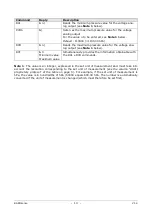
Page 13: ...ets n as the maximum pressure value for the current analog output For the value n to be entered see Note 1 below Default 110000 1100 00 hPa RAH n Reads the maximum pressure value for the current ana log output see Note 1 below RAF 0 Minimum value Maximum value Simultaneously provides the information obtainable with the RAL e RAH commands Voltage output CVOn Enable disable the offset of the voltage...

Page 14: ...below RVF 0 Minimum value Maximum value Simultaneously provides the information obtainable with the RVL e RVH commands Note 1 The value is an integer expressed in the set unit of measurement and must take into account the resolution corresponding to the set unit of measurement see the column ASCII proprietary protocol of the table on page 5 For example if the set unit of measurement is hPa the val...

Page 15: ...the set unit of measurement see table on page 5 for the resolution 16 bit Integer 3 Power supply voltage in Volt x10 16 bit Integer 4 Internal temperature in the set unit of measurement x10 16 bit Integer 5 Error register 0 no error 1 pressure error 2 internal temperature error 3 pressure and internal temperature error 16 bit Integer Coils Address Description Format 0 Set 1 to restore the factory ...

Page 16: ...4 8O1 5 8O2 N no parity E even parity O odd parity 16 bit Integer 2 Instrument address for the MODBUS RTU protocol 1 247 default 1 16 bit Integer 3 Pressure unit of measurement 0 Torr 1 Pa 2 hPa 3 kPa 4 mbar 5 psi 6 kg cm2 7 mmH2O 8 mmHg 9 mmH2O 10 inHg 11 atm 12 bar Default 2 hPa 16 bit Integer 4 Offset added to the measured pressure value For the value see Note 3 below The offset must be within ...

Page 17: ...r 2 Note 2 The value is a 32 bit integer two consecutive registers starting from the one indicated must be accessed to read it The register with lower address contains the least significant bits Note 3 The value is an integer expressed in the set unit of measurement and must take into account the resolution corresponding to the set unit of measurement see the column Modbus protocol IR 0 of the tab...

Page 18: ... well as the specific measures described in this manual are followed The instrument proper operation and operating safety can be ensured only in the cli matic conditions specified in this manual Do not use the instruments in places where there are Corrosive or flammable gases Direct vibrations or shocks to the instrument High intensity electromagnetic fields static electricity User obligations The...

Page 19: ...er supply Includes adapter cable with jack connector on the power supply side and free wires on the instrument side HP3517ITC1 2 Temperature and relative humidity combined probe 4 pole M12 con nector T RH measuring range 40 105 C 0 100 Stem di mensions Ø14 x 135 mm Material PBT Cable length 2 m HD9007A 1 12 ring protection from solar radiations Supplied with mounting bracket For the HP3517ITC1 pro...

Page 20: ...BAROsense 20 V1 2 NOTES ...

Page 21: ...BAROsense 21 V1 2 NOTES ...

Page 22: ...BAROsense 22 V1 2 NOTES ...

Page 23: ......

Page 24: ...arranty included in the manual of the product For any dispute the competent court is the Court of Padua The Italian law and the Convention on Contracts for the International Sales of Goods apply TECHNICAL INFORMATION The quality level of our instruments is the result of the continuous product development This may lead to differences between the information reported in the manual and the instrument...

Reviews: