background image


10 

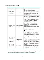
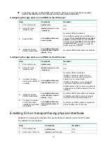
Configuring an EVI tunnel 

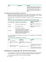
Step Command 

Remarks 

1. 

Enter system view. 

system-view 

N/A 

2. 

Create an EVI 
tunnel interface and 
enter tunnel 
interface view. 

interface tunnel


number mode evi


By default, no tunnel interface exists. 

The endpoints of a tunnel must use the same tunnel 
mode. 

For more information about this command, see 
tunneling commands in 

Layer 3—IP Services 

Command Reference

3. 

Specify a source IP 
address or interface 
for the tunnel. 

source

 { 

ipv4-address

 | 

interface-type 
interface-number

 } 

By default, no source IP address or source interface 
is specified for any tunnel. 

The source interface can be a Layer 3 Ethernet 
interface, Layer 3 aggregate interface, VLAN 
interface, or Layer 3 loopback interface. For more 
information about the 

source

 command, see 

tunneling commands in 

Layer 3—IP Services 

Command Reference

EVI uses the specified address or the primary IP 
address of the specified source interface as the 
source IP address of tunneled packets on the 
transport network. 

EVI networks can share a tunnel source IP address 
or interface. 

You must specify the same source IP address or 
interface for tunnels that use the same 
transport-facing physical interface. 

 IMPORTANT: 

To avoid forwarding failure, do not use a GRE tunnel 
interface or its IP address (configure with the 

ip 

address

 command in tunnel interface view) as the 

source interface or IP address of an EVI tunnel. For 
more information about GRE, see 

Layer 3—IP 

Services Configuration Guide

4. 

Configure the EVI 
link keepalive 
interval and the 
maximum number 
of keepalive 
transmissions. 

keepalive 

seconds


times

 ] ] 

By default, a keepalive packet is sent every five 
seconds and the maximum number of transmissions 
is two.  

If no reply is received from the remote end on an EVI 
link after the maximum number of keepalive 
transmissions is reached, the local end considers the 
EVI link as having failed. 

5. 

(Optional.) 
Generate a GRE 
key for tunneled 
packets based on 
their VLAN IDs. 

gre key


vlan-id 

By default, EVI tunneled packets do not contain a 
GRE key. 

The GRE key setting must be the same across an 
EVI network. Perform this step if any remote edge 
devices generate VLAN ID-based GRE keys for EVI 
tunneled packets. 


NOTE: 

In addition to the EVI-specific commands described in this section, you can configure generic tunnel 
interface commands on an EVI tunnel interface. These tunnel commands and tunneling basics are 
described in the tunneling configuration in 

Layer 3—IP Services Configuration Guide


Summary of Contents for H3C S7500E Series

Page 1: ...H3C S7500E Switch Series Comware 7 EVI Configuration Guide New H3C Technologies Co Ltd http www h3c com Software version Release 7568 Document version 6W101 20180802...

Page 2: ...Blade Comware ITCMM and HUASAN are trademarks of New H3C Technologies Co Ltd All other trademarks that may be mentioned in this manual are the property of their respective owners Notice The informatio...

Page 3: ...and keywords that you enter literally as shown Italic Italic text represents arguments that you replace with actual values Square brackets enclose syntax choices keywords or arguments that are optiona...

Page 4: ...icons Convention Description Represents a generic network device such as a router switch or firewall Represents a routing capable device such as a router or Layer 3 switch Represents a generic switch...

Page 5: ...ardware model configuration or software version It is normal that the port numbers sample output screenshots and other information in the examples differ from what you have on your device Documentatio...

Page 6: ...ling EVI on transport facing physical interfaces 12 Tuning EVI IS IS parameters 13 EVI IS IS configuration task list 13 Creating an EVI IS IS process 13 Optimizing an EVI IS IS network 14 Specifying a...

Page 7: ...achine migration Layer 2 connectivity extension issues EVI resolves the following Layer 2 connectivity extension issues Site independence EVI keeps protocol failures such as broadcast storms from prop...

Page 8: ...twork can convey multiple VLANs but one VLAN can map to only one EVI network Each EVI network has separate network parameters and independently forwards traffic As shown in Figure 3 EVI network 1 exte...

Page 9: ...ish and maintain EVI links and exchange network membership information in an EVI network ENDS An EVI neighbor discovery server maintains all neighbor information in an EVI network An EVI network can h...

Page 10: ...m to learn unicast MAC addresses in their local sites called local MAC addresses If the device learns the source MAC address when it sends out a packet at the egress execute the mac address mac learni...

Page 11: ...tocol header In the outer IP header the source IP address is the source edge device s tunnel source IP address and the destination IP address is the destination edge device s tunnel source IP address...

Page 12: ...ets you can use the ARP flood suppression feature see ARP flood suppression to reduce ARP broadcasts Destination unknown unicast or multicast frame Floods the frame to all internal interfaces in the V...

Page 13: ...the MAC address of IP2 2 Site A s edge device floods the ARP requests out of all interfaces including the EVI tunnel interfaces 3 Site B s edge device de encapsulates the ARP request and broadcasts t...

Page 14: ...llow these hardware restrictions You can enable EVI only on interfaces on the following modules SC interface modules LSQM2GT24PTSSC0 LSQM2GT24TSSC0 SG interface modules The S7503E M switch does not su...

Page 15: ...for special multicast MAC addresses that require Layer 2 inter site forwarding but cannot be learned into the MAC address table Configuring EVI basic features All tasks in this section are required fo...

Page 16: ...he same transport facing physical interface IMPORTANT To avoid forwarding failure do not use a GRE tunnel interface or its IP address configure with the ip address command in tunnel interface view as...

Page 17: ...l interface view interface tunnel number mode evi N A 3 Specify extended VLANs evi extend vlan vlan list By default no VLANs are specified as extended VLANs on any EVI tunnel To specify more extended...

Page 18: ...face tunnel number mode evi N A 3 Configure the edge device as the ENDC of an ENDS evi neighbor discovery client enable server ip By default ENDC is disabled If ENDS is enabled on the EVI tunnel inter...

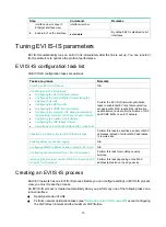
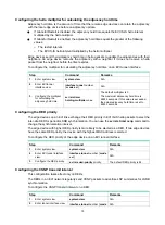
Page 19: ...S network optimization tasks to enable fast EVI link failure detection set appropriate MAC reachability information update interval and control the volume of LSP and CSNP traffic on an EVI network Spe...

Page 20: ...same as the EVI tunnel interface number The EVI IS IS process takes effect after you configure extended VLANs on the tunnel interface Optimizing an EVI IS IS network Perform the tasks in this section...

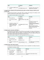
Page 21: ...mer holding multiplier value The default multiplier is 3 The maximum adjacency hold time is 65535 seconds If this value is exceeded the actual adjacency hold time is set to 65535 seconds Configuring t...

Page 22: ...interface cannot send LSP segments Configuring the maximum LSP lifetime EVI edge devices add a lifetime in each LSP they have advertised and update LSPs regularly or when MAC reachability information...

Page 23: ...I Link interface in down state NotReady The EVI link is not monitored This situation occurs when the Track module or the monitoring module is not ready for example the Track module is restarting or th...

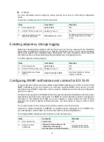
Page 24: ...P notifications and context for EVI IS IS To report critical EVI IS IS events to an NMS enable SNMP notifications for EVI IS IS For EVI IS IS SNMP notifications to be sent correctly you must also conf...

Page 25: ...device is a DED its hello interval is one third of the hello interval set by using the evi isis timer hello command To configure Graceful Restart for an EVI IS IS process Step Command Remarks 1 Enter...

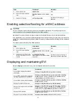
Page 26: ...ging command To enable EVI ARP flood suppression Step Command Remarks 1 Enter system view system view N A 2 Enter EVI tunnel interface view interface tunnel number mode evi N A 3 Enable EVI ARP flood...

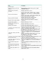
Page 27: ...of VLANs evi selective flooding mac address mac address vlan vlan id list By default selective flooding is disabled for all MAC addresses Displaying and maintaining EVI Execute display commands in an...

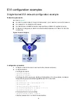
Page 28: ...ber vlan vlan id slot slot number count display evi mac address interface tunnel interface number mac address mac address vlan vlan id slot slot number In IRF mode Display remote MAC addresses display...

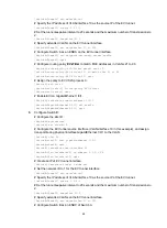
Page 29: ...other Details not shown 2 Configure Switch A Configure the site ID SwitchA system view SwitchA evi site id 1 Configure the EVI tunnel source interface VLAN interface 10 in this example and assign tra...

Page 30: ...0 1 SwitchA interface gigabitethernet 1 0 1 SwitchA GigabitEthernet1 0 1 evi enable SwitchA GigabitEthernet1 0 1 quit 3 Configure Switch B Configure the site ID SwitchB system view SwitchB evi site id...

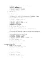
Page 31: ...EVI tunnel interface SwitchC Tunnel1 evi network id 1 Specify the IP address of VLAN interface 10 as the source IP of the EVI tunnel SwitchC Tunnel1 source 1 1 3 1 Set the tunnel keepalive interval t...

Page 32: ...i neighbor discovery client summary Status I Init E Establish P Probe Interface Local Address Server Address Network ID Reg Auth Status Vpn instance Tunnel1 1 1 1 1 1 1 1 1 1 15 disabled E No Vrf Disp...

Page 33: ...el keepalive enabled Period 20 s Retries 2 Network ID 1 Tunnel protocol transport GRE_EVI IP Output queue Urgent queuing Size Length Discards 0 100 0 Output queue Protocol queuing Size Length Discards...

Page 34: ...rface SwitchC display interface tunnel 1 Tunnel1 Current state UP Line protocol state UP Description Tunnel1 Interface Bandwidth 64 kbps Maximum transmit unit 64000 Internet protocol processing Disabl...

Page 35: ...1 Flags 0x2 MAC address 0002 0100 0002 Interface EVI Link1 Flags 0x2 MAC address 0002 0100 0003 Interface EVI Link1 Flags 0x2 The output shows that Switch C can receive MAC addresses in VLAN 100 from...

Page 36: ...Site4 Tunnel101 source 172 16 4 1 Site4 Tunnel101 evi network id 1 Site4 Tunnel101 evi extend vlan 100 101 Site4 Tunnel101 evi neighbor discovery server enable Site4 Tunnel101 quit Configure the netwo...

Page 37: ...agement EVI network Site1 interface tunnel 102 mode evi Site1 Tunnel102 source 172 16 1 1 Site1 Tunnel102 evi network id 2 Site1 Tunnel102 evi extend vlan 4000 Site1 Tunnel102 evi neighbor discovery c...

Page 38: ...em ID Expire Created Time 172 16 1 1 000F 0001 0001 19 2013 01 01 00 19 31 172 16 2 1 000F 0001 0002 25 2013 01 01 00 00 43 172 16 3 1 000F 0001 0003 15 2013 01 01 01 00 46 172 16 4 1 000F 0001 0004 2...

Page 39: ...e 15 EVI IS IS LSP lifetime max 16 EVI IS IS LSP refresh interval 16 EVI IS IS LSP transmit interval 16 EVI IS IS LSPs transmit max 16 EVI IS IS process GR 19 EVI IS IS process LSP MAC entries max 19...

Page 40: ...ion 1 8 23 configuration multiple EVI networks 29 configuration single homed network 23 configuration restrictions 8 DED 3 display 21 edge device 3 ENDC 3 ENDP 3 ENDP configuration 11 ENDS 3 feature c...

Page 41: ...ternal interface 3 interval EVI IS IS CSNP transmit interval 15 EVI IS IS hello interval 14 EVI IS IS LSP refresh interval 16 IP routing EVI ARP flood suppression 7 EVI basic configuration 9 EVI confi...

Page 42: ...hbor discovery ND EVI 3 4 EVI ENDC 3 EVI ENDP 3 EVI ENDS 3 EVI MAC address learning 4 network EVI ARP flood suppression 7 20 EVI basic configuration 9 EVI configuration single homed network 23 EVI DED...

Page 43: ...ring EVI IS IS LSP refresh interval 16 configuring EVI IS IS LSP transmit interval 16 configuring EVI IS IS LSPs transmit max 16 configuring EVI IS IS process GR 19 configuring EVI IS IS process LSP M...

Page 44: ...EVI IS IS parameter tuning 13 EVI IS IS process creation 13 EVI selective flooding 7 EVI transport facing physical interface enable 12 EVI tunnel 3 EVI tunnel configuration 10 EVI tunnel edge device a...

Reviews: