background image


Step Command 

Remarks 

4.


Set the duplex mode.


duplex

 { 

auto

 | 

full

 | 

half

 } 

Optional. 
The default setting is 

auto

A fiber port does not support 

half


keyword.  
10-GE interfaces do not support 
this command.  

5.


Set the transmission rate. 

speed

 { 

10

 | 

100 

|

 1000 

|

 auto

 } 

Optional. 
The default setting is 

auto

6.


Restore the default settings. 

default 

Optional. 

7.


Set the intended bandwidth. 

bandwidth


bandwidth-value


Optional. 


Configuring an Ethernet subinterface 

Step Command 

Remarks 

1.


Enter system view. 

system-view 

N/A 

2.


Enter Ethernet interface view. 

interface


interface-type 

interface-number


N/A 

3.


Configure the interface to 
operate in Layer 3 mode. 

port link-mode route 

By default, an Ethernet interface 
operates in Layer 2 mode. 

4.


Return to system view. 

quit 

N/A 

5.


Create an Ethernet 
subinterface. 

interface 

interface-type 

interface-number.subnumber


This command also leads you to 
Ethernet subinterface view. 

6.


Set the interface description. 

description


text


Optional. 
By default, the description of an 

interface is in the format of 

interface-name


Interface

. For 

example, 

GigabitEthernet3/0/2.1 

Interface

7.


Restore the default settings. 

default 

Optional. 


NOTE: 

For the local and remote Ethernet subinterfaces to transmit traffic correctly, configure them with the same
subinterface number and VLAN ID. 


You can configure IP-related settings on an Ethernet subinterface. For more information, see 

Layer 3

IP 

Services Configuration Guide

Bringing up Ethernet interfaces and subinterfaces 

You can use the commands in this section to bring up a single Ethernet interface in Ethernet interface view, 

or to bring up multiple Ethernet interfaces in port group view. 
To bring up Ethernet interfaces: 


Summary of Contents for S9500E Series

Page 1: ...H3C S9500E Series Routing Switches Interface Configuration Guide Hangzhou H3C Technologies Co Ltd http www h3c com Software version S9500E CMW520 R1828P04 Document version 6W182 20140823...

Page 2: ...gine SecPath SecCenter SecBlade Comware ITCMM and HUASAN are trademarks of Hangzhou H3C Technologies Co Ltd All other trademarks that may be mentioned in this manual are the property of their respecti...

Page 3: ...servicing engineers Network administrators working with the S9500E series Conventions This section describes the conventions used in this documentation set Command conventions Convention Description B...

Page 4: ...s attention to important information that if not understood or followed can result in data loss data corruption or damage to hardware or software IMPORTANT An alert that calls attention to essential i...

Page 5: ...ed during installation Installation guide Provides a complete guide to hardware installation and hardware specifications H3C Pluggable SFP SFP XFP Transceiver Modules Installation Guide Guides you thr...

Page 6: ...ware installation software upgrading and software feature configuration and maintenance documentation Products Solutions Provides information about products and technologies as well as solutions Techn...

Page 7: ...rnet interface configuration task list 11 Configuring a manual port group 12 Setting speed options for auto negotiation on an Ethernet interface 12 Configuring storm suppression for an Ethernet interf...

Page 8: ...ii Displaying and maintaining loopback and null interfaces 27 Index 28...

Page 9: ...being executed on both an aggregate interface and its member interfaces can break up the aggregation No limit is set on the maximum number of interfaces in an interface range The more interfaces in an...

Page 10: ...2 Step Command Remarks 4 Perform available commands to configure the interfaces Available commands vary by interface N A 5 Verify the configuration display this Optional...

Page 11: ...thernet subinterfaces Layer 3 aggregate interfaces and Layer 3 aggregate subinterfaces when it is operating in standard mode For more information about system operating modes see Fundamentals Configur...

Page 12: ...t of a combo interface the switch removes the current port settings such as rate duplex mode and MDI if the fiber port does not support them You cannot bind a combo interface with an IRF port For more...

Page 13: ...capsulate packets as SDH frames but the SDH frames have incompatible formats Introduction to the J0 and J1 overhead bytes SDH frames have diversified overhead bytes which perform the operation and mai...

Page 14: ...ailable only when the 10 GE interface is operating in WAN mode Switching the link mode of an Ethernet interface between Layer 2 and Layer 3 CAUTION The switch supports this command when the operating...

Page 15: ...alf duplex mode half Interfaces operating in this mode can either send or receive packets at a given time Auto negotiation mode auto Interfaces operating in this mode determine a duplex mode through a...

Page 16: ...quit N A 5 Create an Ethernet subinterface interface interface type interface number subnumber This command also leads you to Ethernet subinterface view 6 Set the interface description description tex...

Page 17: ...ntrol on an Ethernet interface You can avoid packet drops on a link by enabling flow control at both ends of the link When traffic congestion occurs at the receiving end the receiving end sends a Paus...

Page 18: ...changes to upper layer modules but it generates traps and logs to inform the user to take corresponding actions To configure physical state change suppression on an Ethernet interface Step Command Re...

Page 19: ...u disable loopback testing the rate and duplex mode of the interface restore Configuration procedure To enable loopback testing on an Ethernet interface Step Command Remarks 1 Enter system view system...

Page 20: ...ulk by assigning these interfaces to a port group Even though the settings are made on the port group they are saved on an interface basis rather than on a port group basis You can only view the setti...

Page 21: ...Ethernet 3 0 1 and GigabitEthernet 3 0 2 In this way the transmission rate on both GigabitEthernet 3 0 1 and GigabitEthernet 3 0 2 is limited to 100 Mbps To set speed options for auto negotiation on a...

Page 22: ...rface interface type interface number Enter port group view port group manual port group name Use either command Configurations made in interface view take effect on the current interface only Configu...

Page 23: ...thernet interface uses an RJ 45 connector which comprises eight pins each playing a dedicated role For example pins 1 and 2 transmit signals and pins 3 and 6 receive signals The pin role varies by the...

Page 24: ...k To enable a fiber port to perform one way forwarding when only one fiber is present you can use the port up mode command This command brings up an Ethernet fiber port by force even when no fiber lin...

Page 25: ...f an Ethernet interface When deploying the switch in an OAA networking environment to ensure normal communication between the switch and the OAP card you must set the connection mode of the interface...

Page 26: ...ession Available in any view Display information about a manual port group or all manual port groups display port group manual all name port group name begin exclude include regular expression Availab...

Page 27: ...able packets directly to SONET synchronous payloads and uses the SONET physical layer transmission standard It offers high speed reliable and point to point data connectivity The POS interfaces on you...

Page 28: ...d ietf hdlc Optional The default is PPP 11 Set the interface MTU mtu size Optional The interface MTU in bytes is in the range of 64 to 10240 and defaults to 1500 The maximum MTU you can configure for...

Page 29: ...v6 hardware forwarding you need to configure static routes or routing protocols on it Displaying and maintaining POS interfaces Task Command Remarks Display information about one or all POS interfaces...

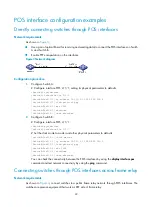
Page 30: ...shutdown SwitchA Pos2 1 1 undo shutdown 2 Configure Switch B Configure interface POS 2 1 1 SwitchB system view SwitchB interface Pos 2 1 1 Set the clock mode to master and other physical parameters to...

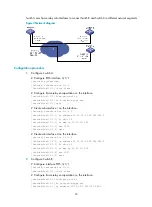
Page 31: ...Pos3 1 1 1 ip address 10 10 10 1 255 255 255 0 SwitchA Pos3 1 1 1 fr dlci 50 SwitchA Pos3 1 1 1 fr map ip 10 10 10 2 50 SwitchA Pos3 1 1 1 mtu 1500 SwitchA Pos3 1 1 1 quit Create sub interface 2 on t...

Page 32: ...the same POS interface you can see the message loopback detected on the screen when executing the display interface command even if you have not enabled loopback If the two switches are directly conn...

Page 33: ...dresses they are usually used as switch identifications Therefore when you configure a rule on an authentication or security server to permit or deny packets generated by a switch you can simplify the...

Page 34: ...as the next hop of a static route to a specific network segment any packets routed to the network segment are dropped Null interface provides you a way to filter packets That is you can simply transmi...

Page 35: ...de regular expression Available in any view Display information about the null interface display interface null brief down begin exclude include regular expression display interface null 0 brief descr...

Page 36: ...nterface null configuration XE procedure configuring interface null 26 Configuring general Ethernet interfaces and subinterfaces 3 Configuring Layer 2 Ethernet interfaces 1 1 Configuring Layer 3 Ether...

Reviews: