background image

44

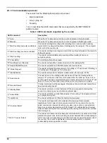
A.1.1.1 Communication protocol

The counter has the following fixed parity and protocol: 

Eight (8) data bits

One (1) stop bit

No parity 

Table 4

 describes the ASCII commands that are supported by the MET ONE 227 

particle counter.

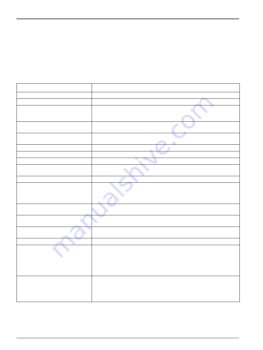
Table 4  ASCII commands supported by the counter

ASCII command

Description

"a" Auto:

When the "a" command is used, the counter is placed in the Auto mode.

"b" Manual:

When the "b" command is used, the counter is placed in the Manual mode. 

"c" Start Counting (computer controlled):

The counter will begin counting without waiting for an even second boundary 
(quick start). Counting will continue until stopped by the computer. The computer 
must control the count cycle.

"d" Start Counting (counter controlled):

The counter will begin counting and control the count cycle based on the counter's 
setting for period.

"e" Stop Counting:

The counter will immediately stop counting without waiting for an even 
second boundary.

"C" Clear Buffer:

The rotating buffer will be erased. 

"D" Send Number of Records:

The counter will send the number of records in the rotating buffer.

"E" Send EPROM Revision:

The counter will send the EPROM number and revision level.

"M" Mode Request:

The counter will send the present mode. If counting, a "C" will be sent. If holding, a 
"H" will be sent. If stopped, an "S" will be sent.

"T" Identify Model:

The counter will send a 4-character model number (for example, 227A). 

"A" Send Record:

The next record in the rotating buffer will be sent. When the rotating buffer is 
empty, a "#" will be sent. Each record is erased from the buffer as it is sent. If no 
count cycles have been completed since the counter was turned on, then a "#" will 
be sent. The record cannot be sent until the current count cycle is complete.

"R" Resend Record:

The last record sent will be sent again. Records sent prior to the last record have 
been permanently erased. 

"h" Standby Mode: 

The counter will enter a mode that turns off the air pump and shuts down the 
sensor to conserve power and reduce equipment wear. 

"g" Active Mode: 

The counter will enter a mode that prepares it for counting. The air pump will turn 
on to purge the air path.

"l" Local Mode: 

The counter will be set to offline (for factory test purposes).

"U" Universal Select: 

The counter will respond to all commands after receiving this command, 
regardless of which select code is programmed into the counter until a counter 
select command is received (functions only when one counter is connected at a 
time). Any counter select command (128 through 191) will disable the Universal 
Select command. Enable this command again by turning off power to the unit and 
then turning it on.

"128-191" Counter Select: 

The counter will respond to all subsequent commands when a number is sent that 
matches the select code, that is, sending a number between 128 (corresponding to 
LOC 0) and 191 (corresponding to LOC 63) that does not equal the select code of 
the counter. The counter is deselected or made unresponsive to computer 
commands by selecting another counter.

Summary of Contents for MET ONE 227

Page 1: ...701094 MET ONE 227 Particle Counter USER MANUAL May 2008 Edition 6 Test Equipment Depot 800 517 8431 99 Washington Street Melrose MA 02176 TestEquipmentDepot com ...

Page 2: ...701094 MET ONE 227 Particle Detector USER MANUAL May 2008 Edition 6 Hach Ultra Analytics Inc 2008 All rights reserved Printed in the U S A ...

Page 3: ......

Page 4: ...he RH T probe 13 3 4 Connections and adjustments 13 Section 4 Operation 15 4 1 Power up 15 4 2 Factory default settings 15 4 3 Manual mode 15 4 4 Automatic mode 16 4 4 1 Unlock the program mode 19 4 4 2 Set display DSP functions 19 4 4 3 Set serial input output SIO functions 21 4 4 4 Set clock CLK functions 21 4 5 Average mode 23 4 6 Concentration mode 24 4 7 Beep mode 26 4 8 Program the temperatu...

Page 5: ...3 A 1 Data analysis for ISO 14644 43 A 1 1 Computer communications 43 Appendix B PortAll Software 47 B 1 Connections 47 B 2 Operation 47 Appendix C DPU 414 Printer 49 C 1 Printer setup 49 C 2 Counter setup for the printer 51 C 3 Interpret the printout 52 Index 53 ...

Page 6: ...r Less than 5 at 2 000 000 particles cubic foot Power 5 W 10 V approximately 6 V with battery pack Light source Laser diode Sample hold times 1 second to 24 hours Count alarms 1 to 9 999 999 counts Data storage 200 samples rotating buffer Count cycles Up to 100 in Auto or Average mode Locations Up to 250 number appears on the printout Output RS232C RS485 for computer Pump type Carbon vane 0 1 cfm ...

Page 7: ...6 Specifications ...

Page 8: ...occur if not observed A symbol if noted on the instrument will be included with a danger or caution statement in the manual This symbol if noted on the instrument references the instruction manual for operation and or safety information Electrical equipment marked with this symbol cannot be disposed of in European public disposal systems after 12 August of 2005 In conformity with European local an...

Page 9: ...tant Note To minimize hazards and ESD risks maintenance procedures not requiring power to the analyzer should be performed with power removed Delicate internal electronic components can be damaged by static electricity resulting in degraded instrument performance or eventual failure The manufacturer recommends the user to take the following steps to prevent ESD damage to the instrument Before the ...

Page 10: ...g parameters For instance the MET ONE 227 particle counter takes 10 minutes to sample 1 cubic foot of air To obtain the counts per cubic foot multiply the results of a 1 minute sample by ten All counts are reported as cumulative counts that is all the reported 0 3 micron particles are 0 3 micron and larger in size 2 3 Theory of operation The MET ONE 227A B particle counter is a combination of a se...

Page 11: ...10 General Information Figure 2 Theory of operation 1 Sample inlet 5 Sample exhaust 2 Sensor 6 Serial data out 3 Pump 7 Control electronics 4 Filter 8 Display ...

Page 12: ... to store or ship the instrument to protect against damage during storage or transportation 3 2 Installation guidelines for the MET ONE 227 particle counter The MET ONE 227 particle counter is ready to use when shipped and is configured in a default mode refer to section 4 2 on page 15 Before the operation of the MET ONE 227 particle counter make sure that the following guidelines are complied to ...

Page 13: ...ic probe to the sensor inlet so that the open end faces the direction of the air stream 3 3 2 Install the purge filter The purge filter refer to Figure 3 on page 11 item 2 is used for the maintenance of the MET ONE 227 particle counter The filter prevents the contamination of the sensor and purges the sensor of accumulated internal particles To install the purge filter 1 Remove the red sensor inle...

Page 14: ...he AC adapter 1 Turn off power to the MET ONE 227 particle counter 2 Attach the AC adapter to the power input jack refer to Figure 5 on page 13 on the bottom of the MET ONE 227 particle counter 3 3 5 Install the RH T probe To install the RH T probe 1 Locate the connector for the RH T probe refer to Figure 4 on page 12 item 1 on top of the MET ONE 227 particle counter 2 Attach the RH T probe to the...

Page 15: ...14 Installation ...

Page 16: ...minute count cycle 1 Press 1 on the front panel refer to Figure 6 The pump will begin to operate The count cycle status will change from Stop to Wait for two seconds while the pump reaches maximum speed The count cycle status refer to Figure 6 item 2 will change to Run during the 1 minute sample and return to Stop at the end of the count cycle The MET ONE 227 particle counter draws 0 1 cubic foot ...

Page 17: ...nter need not be programmed in a sequential order and any parameter may be programmed at any time without affecting the others Figure 7 on page 17 shows an example of a program sampling pattern where a MET ONE 227 particle counter is used to verify the cleanliness of a large room dividing the space into eight sections for a comprehensive measurement Figure 6 LCD display 1 Channel 1 and channel 2 s...

Page 18: ... Gives the average minimum and maximum count for a specified number of count cycles Count Mode Concentration CF or L Approximates count per cubic foot of air CF or count liter of air L Also changes temperature readout from F to C Period Time 1 to 10 seconds selected for count approximation when in Concentration mode Count Mode Beep B One beep after channel 1 and channel 2 count limit is reached an...

Page 19: ...t alarm limit has been exceeded Low Battery When flashing indicates battery needs recharging Program Mode Indicates that the user has entered the mode for changing parameters or limits of the display serial I O or clock functions RUN Begins the count cycle STOP Stops the count cycle before completion data is not saved DSP Top menu name Display for all display parameters SIO Top menu item Serial In...

Page 20: ...e 8 3 Press 1 PROG to enter the Program mode 4 Press 2 INC to unlock the Program mode 5 Press 4 RET to return to the main screen 4 4 2 Set display DSP functions 4 4 2 1 Location number To set the location number 1 Press 2 DSP on the main screen The Location Number screen is displayed refer to Figure 9 2 Press 1 PROG to enter the Program mode 3 Press 2 INC to set the Location Number to 001 4 Press ...

Page 21: ...A repeats count cycles until all the count cycles programmed are complete 5 Press 4 RET The Num Cycles screen is displayed in the Program mode refer to Figure 11 6 Press 2 INC and 3 DEC to select three count cycles If infinity INF is selected the MET ONE 227 particle counter will continue to count cycles until manually stopped 7 Press 4 RET to save the settings and return to the main screen Figure...

Page 22: ...nts of the buffer 4 4 4 Set clock CLK functions 4 4 4 1 Set the date and time To set the date and time 1 Press 4 CLK on the main screen The Date and Time screen is displayed refer to Figure 13 2 Press 1 PROG to enter the Program mode 3 Press 1 to move the cursor along the digits 4 Press 2 INC and 3 DEC to set the current date and time The date and time will appear on the data record for each sampl...

Page 23: ...t area to be tested 2 Place or hold the counter about 4 feet off the floor Make sure that the opening of the isokinetic probe faces directly into the laminar flow 3 Press 1 RUN to initiate counting The display shows three 1 minute samples being taken separated by a 1 second hold time When the three 1 minute samples are complete the MET ONE 227 particle counter will stop the count 4 Move the MET ON...

Page 24: ...ed in the Program mode refer to Figure 16 6 Press 2 INC or 3 DEC to select the required period 7 Press 4 RET to save the settings and return to the main screen 8 Press 1 RUN to begin the count cycle The count status display will display Wait while the pump comes up to speed then display RUN when the MET ONE 227 particle counter takes a sample The MET ONE 227 particle counter will display Hold for ...

Page 25: ...liter based on a programmable period of time The MET ONE 227 particle counter updates the calculation results on the display at 1 second intervals The programmable period sets the size of a calculation window in seconds which is moved each second to incorporate the sample data for the next second The sample data for the oldest second of the previous period is then discarded The MET ONE 227 particl...

Page 26: ...the MET ONE 227 particle counter for the Concentration mode 1 Press 2 DSP on the main screen 2 Press 2 NXT to display the Count mode screen refer to Figure 20 3 Press 1 PROG to enter the Program mode 4 Press 2 INC or 3 DEC to select the Concentration mode 5 Press 4 RET to display the Period screen in the Program mode refer to Figure 21 on page 26 Figure 19 Concentration mode 10 second period 1 10 ...

Page 27: ... displays RUN while the counter takes a sample In the Concentration mode counting continues until 1 STOP is pressed 4 7 Beep mode In the Beep mode a single audible sound beeps once every time a count alarm limit is reached and then once more for every multiple of the count limit For example if the limit is set at 1 000 particles the beep will sound at 1 000 2 000 3 000 and so on There are two size...

Page 28: ...4 7 Press 1 PROG to enter the Program mode 8 Press 1 to move the cursor along the digits 9 Press 2 INC or 3 DEC to set the alarm limits for the required settings time to 1 minute and the Hold time to 1 second refer to Figure 24 10 Press 4 RET to save the settings and return to the main screen 11 Press 1 RUN to begin the count cycle The count status display will display Wait while the pump comes up...

Page 29: ... degree Celsius C or degrees Fahrenheit F To program the temperature display 1 Press 2 DSP on the main screen and then repeatedly press 2 NXT to display the Temperature screen refer to Figure 25 2 Press 1 PROG to enter the Program mode 3 Press 2 INC or 3 DEC to select the Beep mode 4 Press 4 RET to return to the main screen Figure 25 Temperature screen ...

Page 30: ...ns Important Note Never connect or disconnect the sensor cable from the counter when the counter is on 5 2 Clean the sensor To clean the sensor 1 Remove the four screws two on each side from the MET ONE 227 particle counter 2 Remove the two screws from the bracket on the top end of the MET ONE 227 particle counter 3 Open the two halves of the unit apart Pull the back of the unit slightly downward ...

Page 31: ...30 Maintenance ...

Page 32: ...ticle sensor is no longer operating within acceptable limits Any count data taken during this alarm condition is disregarded as inaccurate The primary cause of this condition is sensor contamination When this alarm occurs 1 Purge the sensor by attaching the purge filter that is supplied with the counter to the sensor inlet on top of the counter 2 Place the counter on the stand and attach the AC ad...

Page 33: ...estore it to optimum operation 6 3 1 Disassemble and clean the pump Prerequisites 1 27 mm or 1 5 mm Allen wrench To disassemble and clean the pump 1 Open the counter as described in steps 1 to 3 of section 5 2 on page 29 2 Remove the pump from the chassis clip 3 Unplug the pump electrical connection 4 Disconnect the tubing from the pump Note Make note of the tubing that is attached to the Vacuum V...

Page 34: ...Push the bracket to one side and remove it from the pump refer to Figure 29 7 Remove the top of the pump refer to Figure 30 and locate the locator pin Figure 28 Loosening of the set screw 1 Hex key wrench 1 Figure 29 Removal of the bracket 1 Bracket 1 Figure 30 Removal of the top of the pump 1 Locator pin 2 Top of the pump 1 2 ...

Page 35: ... 32 on page 34 and Figure 33 on page 34 and make sure that the rotor turns freely 10 Perform steps 1 to 9 in the reverse order to assemble the pump into the counter Figure 31 Removal of the pump body 1 Pump body 1 Figure 32 Removal of carbon vanes 1 Carbon vane 1 Figure 33 After removal of carbon vanes ...

Page 36: ...r 2 Turn on power to the MET ONE 227 particle counter 3 Press 1 RUN to initiate a count cycle and turn on the pump 4 Hold the pump motor still 5 Rotate the entire pump head in a 180 arc refer to Figure 34 6 As the pump head is rotated listen for the point where the Revolutions per Minute RPMs are the greatest 7 Keep the pump head steady and tighten the set screw Figure 34 Rotation of the pump head...

Page 37: ...36 Troubleshooting ...

Page 38: ...he high pressure diffuser is connected to the sensor inlet tubing of the MET ONE 227 particle counter The diffuser permits the direct sampling of pressurized air at pressures that range from 30 to 150 psi RS485 converter The RS485 converter converts data from the RS232 to RS485 format for longer serial networking to a computer Consult Technical Support for installation 7 1 Accessories Description ...

Page 39: ...readsheet format The software performs calculations as per the FS 209E and ISO 14644 standards The software includes an adapter for use with a standard 9 pin serial cable Refer to Appendix B on page 47 for additional information Carrying case The carrying case protects the particle counter during shipment and storage Figure 38 PortAll software 2084045 Figure 39 Carrying case 2080878 ...

Page 40: ...Oregon 97526 Email TechSupportGP hachultra com Website www hachultra com International customers By Telephone 41 22 594 64 00 By Fax 41 22 594 64 99 By Mail Hach Ultra Service Department 6 route de Compois C P 212 CH 1222 Vésenaz Geneva Switzerland Website www hachultra com Information required Your name Model number Your phone number Serial number Your company name Comment or question Your fax nu...

Page 41: ... location within the same country as the service support center This warranty shall not apply to any defect failure or damage caused by improper use or maintenance or by inadequate maintenance or care This warranty shall not apply to damage resulting from attempts by personnel other than Hach Ultra representatives or factory authorized and trained personnel to install repair or service the instrum...

Page 42: ... A Radiated EN 55011 1991 Class A Conducted EN 61326 1998 EN 50082 1 1997 Immunity EN 61000 4 2 Electrostatic Discharge EN 61000 4 3 Electromagnetic Field EN 61000 4 4 Electrical Fast Transient EN 61000 4 5 Surge Test Common and Differential mode EN 61000 4 6 3 Volt Modulated Interfering Signal EN 61000 4 8 Susceptible Magnetic Fields EN 61000 4 11 Voltage Interruption Test EN 61010 1 1993 Amendme...

Page 43: ...42 Certification ...

Page 44: ...he PortAll software A 1 1 Computer communications The MET ONE 227 particle counter has been setup for RS232 and Rs485 serial data communications capabilities RS232 serial interface circuitry Provides asynchronous communications between the counter and computer RS485 serial network circuitry Provides asynchronous communications between up to 64 counters and a controlling computer A terminal program...

Page 45: ...Record The next record in the rotating buffer will be sent When the rotating buffer is empty a will be sent Each record is erased from the buffer as it is sent If no count cycles have been completed since the counter was turned on then a will be sent The record cannot be sent until the current count cycle is complete R Resend Record The last record sent will be sent again Records sent prior to the...

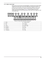
Page 46: ... Each data point is preceded by a 3 character tag that identifies the type of data that follows in the next six data characters Figure 41 shows an example of the serial communications format of a two channel particle counter CRLF is the carriage return and line feed command Figure 41 Serial communications format example 1 Status 9 Relative humidity 2 Date 10 Location 3 Time 11 Checksum 4 Period 12...

Page 47: ...46 ...

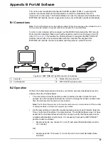
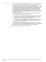
Page 48: ... on B 2 Operation Perform the following procedures to make sure that an accurate classification result is obtained from the PortAll software The data returned from the particle counter contains a location number for each sample Use the front panel instrument controls to change the location number each time the instrument is moved to a new location Note The PortAll software relies on the location n...

Page 49: ...atically normalized Note Make sure that the address value does not exceed 31 PortAll will not recognize an instrument whose address is outside the range of 0 to 31 For ISO 14644 1 PortAll stores the ISO classification limits internally in a table as counts per cubic meter To obtain accurate classifications the data in the spreadsheet must be normalized to counts per cubic meter For FS209E PortAll ...

Page 50: ... match the settings in Table 5 on page 50 no changes are necessary 4 Press the FEED button to exit the DIP switch setting mode If changes are necessary proceed to step 5 5 Press the ONLINE button to begin the programming of DIP SW 1 settings The printer will print Dip SW 1 and open the first switch position 6 Press the FEED button to set the first DIP switch position off The printer will print 1 O...

Page 51: ...t the DIP SW programming mode after the last position is set and print DIP SW setting complete Make sure that the printer is online when the programming is complete Table 5 DIP switch settings Dip switch 1 1 OFF Input Serial 2 ON Printing Speed High 3 ON Auto Loading On 4 ON Auto LF On 5 ON Setting Command Enable 6 ON Printing 7 ON Density 8 ON 72 Dip switch 2 1 ON Printing Columns 40 2 ON User Fo...

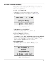
Page 52: ... Press 1 PROG to enter the Program mode 4 Press 2 INC or 3 DEC to select the required RS232 mode 5 Press to return to the main screen There are three RS232 modes to select from Normal mode Disables the printer function Print A Record Prints the particle count results after completion of each count cycle Print The Buffer Prints all the count cycles contained in the rotating buffer Data is removed f...

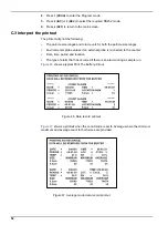
Page 53: ...article size ranges Environmental probe values if an external probe is connected to the counter Date time period and location The type of alarm that has occurred if there is an alarm during a sample run Figure 46 shows a typical Print The Buffer printout Figure 47 shows a printout when the count mode is set to Average where the minimum maximum and average count for both sizes are provided Figure 4...

Page 54: ...fety 8 location number 19 M manual mode operation 15 memory buffer clearance 21 O Operation 47 operation PortAll software 47 operation theory 9 P period and hold times 22 power up operation 15 Precautionary labels 7 printout interpretation 52 product information general 9 program mode unlock 19 protocol communication 44 pump disassembly 32 pump maintenance 32 R relative humidity and temperature pr...

Page 55: ......
Page 56: ...el électrique en Europe doivent désormais retourner le matériel usé ou périmé au fabricant pour élimination sans frais pour l utilisateur Remarque Veuillez vous adresser au fabricant ou au fournisseur du matériel pour les instructions de retour du matériel usé ou périmé aux fins d élimination conforme Ce document est important Conservez le dans le dossier du produit ITALIAN Le apparecchiature elet...

Page 57: ...an elektrische apparaten voortaan hun oude of afgedankte apparatuur kosteloos voor recycling of vernietiging naar de producent terug te brengen Nota Als u apparatuur voor recycling terugbrengt moet u contact opnemen met de producent of leverancier voor instructies voor het terugbrengen van de afgedankte apparatuur voor een juiste verwerking Belangrijk document Bewaar het bij de productpapieren POL...

Page 58: ...e de USA AND REST OF WORLD Hach Company P O Box 389 Loveland Colorado 80539 0389 USA Phone 800 227 4224 Fax 970 669 2932 techhelp hach com Dieses Informationsblatt enthält Angaben die ausschließlich für den Export dieses Gerätes in die Volksrepublik China erforderlich sind This document contains information which is only required for the export of this instrument into the People s Republic of Chin...

Page 59: ...s are property of their respective owners Specifications subject to change without notice 99 Washington Street Melrose MA 02176 Phone 781 665 1400 Toll Free 1 800 517 8431 Visit us at www TestEquipmentDepot com ...

Reviews: