A4
4.
Theory of Operation
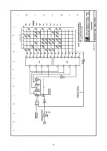
The buffer memory is installed in the DKB-2010 keyboard between the output of the keyencoder and the
input of the circuit board. In the standard keyboard, keystrokes are translated into a seven-bit ASCII code
by the keyencoder. These codes are fed directly to the ROM, where they are converted to the correct bit
pattern for either Morse or RTTY transmission, depending on the mode selected
.
The heart of the buffer is an eight-bit parallel first-in, first-out (FIFO) buffer. Characters from the
keyencoder are clocked into the buffer on data Lines A
0
through A
6
each time a keystroke occurs. The
character code bits ripple through the buffer stages toward the output end. They are clocked out of the
buffer, one eight-bit code at a time, into the keyboard logic circuits when the
ENABLE
signal from the logic
circuit indicates that the keyboard is ready to receive them. If the buffer input rate exceeds the output rate,
the character codes ripple through the buffer and stack up at the output end, awaiting transfer to the logic
circuit.
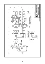
Each eight-bit buffer consists of two four-bit FIFO buffer IC's operating in parallel (IC's 7 and 8 in the
schematic diagram). The buffers are capable of storing up to 64 eight-bit character codes. In the 128-key
model, two additional buffers (IC's 10 and 11), in the same parallel configuration, are connected in series
with the first two buffers to provide a storage capacity of 128 eight-bit codes.
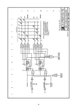
Additional control logic senses closure of one of the automatic character sequence keys (QBF, HERE IS,
CQ and AUX) and enters a special code into the FIFO buffers. When this code reaches the buffer output, it is
sensed by one of a series of logic gates which actuates the appropriate character sequencer in the
keyboard.
Characters (or keystrokes) from the keyswitch board enter the buffer whenever the READY line from the
keyencoder goes high. The stored characters are clocked out of the buffer by a transition of the
ENABLE
line, which occurs whenever the keyboard logic circuits are ready to receive a new character code. When the
buffer is full, the R
i
(input ready) terminal of the buffer goes low, driving a switching transistor (Q501) into
conduction. The BUFFER FULL Lamp, which serves as the transistor's collector load, then lights.
The output of the buffer memory is controlled by IC-5, which forms a flip-flop driven by two control
gates. When the AUX key is pressed along with one of the SHIFT keys, the flip-flop is set. An output from
the flip-flop controls the READY line, which when high normally indicates that one or more characters have
been stored in the buffer awaiting transfer to the keyboard logic. If the flip-flop is set, the READY line is held
low, and the keyboard logic is not notified that characters are stored in the buffer. Hence, no clock pulses
return via the
ENABLE
line. Incoming characters are stored in the buffer, but are not transmitted.
When the SHIFT and CQ keys are pressed simultaneously, the flip-flop is reset, and the READY line is
allowed to go high. The keyboard logic then generates a transition on the
ENABLE
line, clocking the first
character out of the buffer. The process repeats until all stored characters have been transmitted.
The buffers may be cleared of all contents by pressing the SHIFT and HERE IS keys simultaneously. A
NOR gate senses this combination of key closures and drives the
CLEAR BUFFER
line low, resetting all
stages of the shift registers.
Consult the DKB-2010 instruction manual for a complete discussion of the keyboard logic circuitry.
Summary of Contents for DKB-2010
Page 1: ......
Page 20: ...18...
Page 39: ...37 Table 4 3 ROM Converter Input and Output Codes...
Page 52: ...50 Figure 6 1 Logic Circuit Board Test Points...
Page 53: ...51 Figure 6 2 Keyswitch Circuit Board Test Points...
Page 54: ...52 Figure 6 3 Power Supply Circuit Board Test Points...
Page 57: ...55 Table 6 4 DKB 2010 Wire List...
Page 63: ...61...
Page 64: ...62...
Page 65: ...63...
Page 67: ...65...
Page 69: ...67...
Page 71: ...69...
Page 73: ...71...
Page 75: ...73...
Page 77: ...75...
Page 79: ...77...
Page 81: ...79...
Page 83: ...81...
Page 85: ...83...
Page 87: ...85...
Page 89: ...87...
Page 91: ...89...
Page 92: ...90...
Page 93: ...91...
Page 94: ...92...
Page 95: ...93...
Page 96: ...A1 EXTENDED MEMORY OPTION FOR THE DKB 2010 KEYBOARD INSTRUCTION MANUAL...
Page 100: ...A5...
Page 101: ...A6...

