86
Configuring QCN
Quantized Congestion Notification (QCN) is an end-to-end congestion notification mechanism that
can reduce packet loss and delay in Layer 2 networks by actively sending reverse notifications. QCN
is primarily used in data center networks.
Basic concepts
•
Reaction point (RP)
—A source end host that supports QCN.
•
Congestion
point
(CP)
—A congestion detection device that is enabled with QCN.
•
Congestion notification message (CNM)
—A message transmitted by a CP to an RP when a
queue on the CP is congested.
•
Congestion controlled flow (CCF)
—A flow of frames with the same priority value. A CP
assigns frames of the same CCF to one queue before forwarding them.
•
Congestion notification tag (CN tag)
—Identifies a CCF. Devices in a CND must be able to
process packets with a CN tag.
•
Congestion notification priority (CNP)
—An 802.1p priority that is enabled with QCN. The
value of that 802.1p priority is called a congestion notification priority value (CNPV).
•
Congestion notification domain (CND)
—A set of RPs and CPs with QCN enabled for a
CNPV.
•
Congestion point identifier (CPID)
—An 8-byte unique identifier for a CP in the network.
•
Quantized
feedback
(QntzFb)
—A 6-bit quantized feedback value indicating the extent of
congestion.
QCN message format
Data flow format
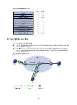
An RP can add CN tags to outgoing Ethernet frames to distinguish between CCFs. A CN tag defines
a CCF.
As shown in
, the CN tag contains the following fields:
•
EtherType
—Indicates the Ethernet type of the data packet, 2 bytes in length and assigned a
value of 0x22E9.
•
RPID
—Locally assigned and 2 bytes in length. When receiving a CNM, the RP uses this field to
identify the CCF that causes congestion and then rate limits that CCF.
When only one CCF exists, the RP may not add a CN tag to packets. In this case, the triggered CNM
carries a CN tag with the RPID as 0.
A CN tag is confined within its CND. When a packet leaves a CND, the CN tag is stripped off.
Figure 31 Data flow format
Summary of Contents for FlexFabric 5940 Series
Page 23: ...17 Figure 3 QoS processing flow ...
Page 84: ...78 Figure 26 MPLS label structure ...
Page 91: ...85 Switch burst mode enable ...


