background image

HITACHI INVERTER

EASY-SEQUENCE  
PROGRAMMING SOFTWARE

㧔㧱㨦㧿㧽㧕

INSTRUCTION MANUAL

㧴㧵㨀㧭㧯㧴㧵

Read through this Instruction Manual, and keep it handy for future reference.

NT2021XA

Summary of Contents for NT2021XA

Page 1: ...HITACHI INVERTER EASY SEQUENCE PROGRAMMING SOFTWARE㧔㧱㨦㧿㧽㧕 INSTRUCTION MANUAL 㧴㧵㨀㧭㧯㧴㧵 Read through this Instruction Manual and keep it handy for future reference NT2021XA ...

Page 2: ... together with optional products also read the manuals for those products Note that this Instruction Manual and the manual for each optional product to be used should be delivered to the end user of the inverter Handling of this Instruction Manual The contents of this Instruction Manual are subject to change without prior notice Even if you lose this Instruction Manual it will not be resupplied so...

Page 3: ... according to circumstances Be sure to follow every safety instruction which contains important safety information Also focus on and observe the items and instructions described under Notes in the text 㧍 CAUTION WARNING During trial operation of the inverter with a user program a user program error may cause the motor driven by the inverter to run uncontrollably Be sure to implement safety measure...

Page 4: ... Safety Instructions ...

Page 5: ... 6 6 Numeric values 2 6 2 3 Program Control Instructions 2 7 entry and end statements 2 7 sub and end sub statements 2 7 goto statement 2 8 on trip goto statement 2 8 ifs then else end if statements 2 9 if statement 2 10 for next loop statements 2 11 while loop statement 2 12 until loop statement 2 13 select case syntax statement 2 14 call statement 2 15 inc statement 2 15 dec statement 2 16 Label...

Page 6: ... 2 31 eepwrt 2 32 rtcset on rtcset off 2 33 2 7 Other Reserved Variables 2 34 U 00 to U 31 2 34 UL 00 to UL 07 2 34 SET Freq 2 35 ACCEL 2 36 DECEL 2 37 XA 0 to XA 2 2 38 YA 0 to YA 2 2 39 TD 0 to TD 7 TDw 2 41 2 8 Inverter Montor Variables 2 42 FM 2 42 Iout 2 43 Dir 2 44 PID FB 2 45 F CNV 2 45 Tmon 2 46 Vout 2 47 Power 2 47 PlsCnt 2 48 POS 2 48 STATUS 2 49 DCV 2 49 RUN Time 2 50 ON Time 2 50 ERR C...

Page 7: ...ose analog input terminal O2 terminal 3 5 7 General purpose analog output terminal FM terminal in SJ700 L700 SJ700B EO terminal in WJ200 3 6 8 General purpose analog output terminal AM terminal 3 6 9 General purpose analog output terminal AMI terminal 3 7 3 4 Switching of Command Input Device 3 8 1 Frequency source setting A001 A201 3 8 2 Run command source setting A002 A202 3 8 3 Accel decel time...

Page 8: ... Contents ...

Page 9: ...xplains the general procedures for creating and executing a user program 1 1 Outline 1 1 1 2 Corresponding Model 1 1 1 3 Specifications 1 1 1 4 Preparation and System Configuration 1 2 1 5 General Flow of Operation and Setup 1 3 1 6 Notice 1 3 ...

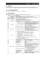
Page 10: ...Chapter 1 Outline of EzSQ ...

Page 11: ...SJ700B Up to 6 terminals Y 00 to Y 05 WJ200 Up to 3 terminals Y 00 to Y 02 General purpose analog output YA 0 Assignable to the FM terminal YA 1 Assignable to the AM terminal YA 2 Assignable to the AMI terminal Only SJ700 Reserved words Instructions 1 Program control instructions Loop for Unconditional branching goto Time control wait Conditional branching if then ifs then select case until and wh...

Page 12: ... or SJ700B via the PC inverter connection cable After completing these preparations you can operate ProDriveNext to create a user program and download it to the inverter The table below lists the main functions of ProDriveNext Please refer to the manual of ProDriveNext for use Function Description Programming support Supports the input editing saving reading and printing of user programs Compilati...

Page 13: ...2 in WJ200 the user program runs automatically after turning on the power 2 1 If the downloaded user program is saved in internal EEPROM of the inverter you can execute the user program even after resetting the inverter power If the downloaded user program is not saved in EEPROM the user program will be deleted when the inverter power is fully shut off You are recommended not to save a created use...

Page 14: ...1 4 Chapter 1 Outline of EzSQ ...

Page 15: ...mming 2 1 Description Format 2 1 2 2 List of Instructions 2 3 2 3 Program Control Instructions 2 7 2 4 Input Output Control Instructions 2 18 2 5 Timer Control Instructions 2 23 2 6 Inverter Control Instructions 2 27 2 7 Other Reserved Variables 2 34 2 8 Inverter Montor Variables 2 42 ...

Page 16: ...Chapter 2 Syntax ...

Page 17: ...e Parameter 1 to 6 fields to describe the arguments required to execute an instruction Up to six arguments can be described as required for the instruction word described on the same line 5 Comment Use the Comment field to describe a comment on each line Note 1 Please describe the instruction in the line that describes the label The program might not upload correctly if the instruction is not desc...

Page 18: ...e Result field displays a calculation result You cannot rewrite the calculation result 4 Comment You can describe a comment about the variable described on the line Note The item that can be uploaded is only Result Definition and Comment cannot be uploaded 3 Multitasking function In WJ200 series two or more programs a maximum of 5 tasks can be simultaneously performed by the multitasking function ...

Page 19: ...ured if ifs condition Starts the structured if statement then Indicates the beginning of instructions to be executed when condition is met instruction set Indicates the instructions to be executed when condition is met else Indicates the beginning of instructions to be executed when condition is not met instruction set Indicates the instructions to be executed when condition is not met end if Ends...

Page 20: ...3 constant and assigns the result to variable 1 variable 1 variable 2 constant variable 3 constant Subtracts variable 3 constant from variable 2 constant and assigns the result to variable 1 variable 1 variable 2 constant variable 3 constant Multiplies variable 2 constant by variable 3 constant and assigns the result to variable 1 variable 1 variable 2 constant variable 3 constant Divides variable...

Page 21: ...r off TD k Stops the specified timer Internal user contact control variable UB ii Fetches internal user contact information and stores it in variable 0 off 1 on variable UBw Fetches internal user contact information and stores it as word data in variable UB ii variable constant Outputs bit data to an internal user contact 0 off 1 on UBw variable constant Outputs word data to an internal user conta...

Page 22: ...07 2147483648 to 2147483647 Frequency setting variable SET Freq 0 to 40000 Acceleration deceleration time setting variable ACCEL DECEL 0 to 360000 Monitoring and other variables See Section 2 8 Inverter Monitor Variables 6 Numeric values㩷 Notation Numeration Remarks Omitted Decimal Decimal number H Hexadecimal Hexadecimal number specifiable only in the Data Window B Binary Binary number specifiabl...

Page 23: ...structions to start and end a subroutine Format Format Description sub subroutine name This instruction indicates the beginning of a subroutine end sub This instruction indicates the end of a subroutine Control is returned to the calling routine Explanation The sub and end sub statements indicate the beginning and end of a subroutine respectively subroutine name Specifies the name of a called subr...

Page 24: ...processing upon the occurrence of an event Format Format Description on trip goto label name This instruction branches processing to the step labeled with label name when the inverter trips Explanation Use this instruction to branch processing to the step labeled with label name when the inverter trips In the SJ700 Series when inverter trips without the description of this instruction the program ...

Page 25: ... The instructions are executed in units of lines in a cycle as explained below instruction set 2 Specifies the instructions to be executed when condition is met The instructions may be described on two or more lines The instructions are executed in units of lines in a cycle as explained below Processing cycle Note that condition is checked in the first cycle and the first instruction in instructio...

Page 26: ...ions 2 Conditional expressions label name Specifies the label name of the branch target step line Processing cycle Note that condition check and branch processing are executed in the same cycle Refer to the statement execution sequence indicated by parenthesized numbers in the comment fields of the sample programs below Sample program Label Mnemonic parameter1 parameter2 parameter3 parameter4 para...

Page 27: ... value of variable to be applied at the beginning of the loop You can specify a variable name or immediate value i e a value that can be entered directly The immediate value must be an integer ranging from 0 to 127 To use a larger numerical value preset the value in a variable and specify the variable as start value end value Specifies the limit value at which to exit the loop Processing exits the...

Page 28: ...quence of execution 㩷 for U 00 0 3 1 㩷 䋺 1 㩷 㩷 㩷 㩷 Y 00 1 㩷 㩷 㩷 㩷 䋺 2 5 8 㩷 Y 00 0 㩷 㩷 㩷 㩷 䋺 3 6 9 㩷 next 㩷 㩷 㩷 㩷 㩷 䋺 4 7 10 㩷 Y 00 1 㩷 㩷 㩷 㩷 䋺 11 while loop statement Instruction to conditionallyexecute a pre conditioned loop Format Format Description while condition instruction set wend This instruction executes instruction set while condition is met Note that condition is checked before the exe...

Page 29: ...nation This instruction executes instruction set repeatedly until condition is met Note that condition is checked after the execution of instruction set Execute instruction set Is condition met Yes No Sample program Condition X 00 0 is met after the loop is executed twice Label Mnemonic parameter1 parameter2 parameter3 parameter4 parameter5 Sequence of execution 㩷 until X 00 1 㩷 㩷 䋺 1 㩷 㩷 㩷 5 9 㩷 ...

Page 30: ...l value n 1 Explanation This instruction executes instruction set 1 to instruction set n 1 described in a case statement when conditional variable matches conditional value 1 to conditional value n 1 in the case statement respectively If the case else statement is described instruction set n is executed when conditional variable does not match any of conditional value 1 to conditional value n 1 Sa...

Page 31: ...㩷 㩷 Call subroutine SUB1 㩷 㩷 䋺 㩷 㩷 㩷 㩷 㩷 㩷 㩷 end 㩷 㩷 㩷 㩷 㩷 㩷 㩷 㩷 㩷 㩷 㩷 㩷 㩷 㩷 㩷 sub SUB1 㩷 㩷 㩷 㩷 Called subroutine 㩷 㩷 䋺 㩷 㩷 㩷 㩷 㩷 㩷 㩷 Y 00 1 㩷 㩷 㩷 㩷 㩷 㩷 䋺 㩷 㩷 㩷 㩷 㩷 㩷 㩷 sub end 㩷 㩷 㩷 㩷 㩷 㩷 inc statement Instruction to increment a variable Format Format Description inc variable This instruction increments variable by 1 Explanation This instruction adds 1 to the value of variable Sample program Code...

Page 32: ...00 㩷 㩷 㩷 Output the content of U 00 to terminals Y 00 to Y 05 㩷 wait 0 5 㩷 㩷 㩷 㩷 Wait 0 5 seconds 㩷 goto LOOP 㩷 㩷 㩷 㩷 㩷 㩷 end 㩷 㩷 㩷 㩷 㩷 㩷 Data area Data Window U 00 255 U 01 63 Label definition statement Statement to define a label Format Format Description label name This statement defines label name Explanation Use this statement to define label name to be used in the goto or other instructions ...

Page 33: ...pse the next instruction is executed Format 3 This instruction makes processing wait until condition is met After condition is met the next instruction is executed Sample program Sample 1 Format 1 Label Mnemonic parameter1 parameter2 parameter3 parameter4 parameter5 㩷 㩷 㩷 䋺 㩷 㩷 㩷 㩷 㩷 㩷 㩷 wait 1 00 㩷 㩷 㩷 㩷 Wait 1 second 㩷 Y 00 1 㩷 㩷 㩷 㩷 㩷 㩷 䋺 㩷 㩷 㩷 㩷 㩷 㩷 Sample 2 Format 2 Label Mnemonic parameter1 ...

Page 34: ...of terminal active state C011 to C018 is reflected in the polarity on or off of contact inputs X 00 to X 07 and Xw When you create a user program consider the on and off states of actual intelligent input terminals 1 to 8 In the WJ200 Series the setting of terminal active state C011 to C017 is reflected in the polarity on or off of contact inputs X 00 to X 06 and Xw When you create a user program ...

Page 35: ...o fetch and store the status data of contact output terminals Y 00 to Y 05 in variable Details of the formats are explained below Format 1 With this format the instruction outputs variable to the ii th bit of contact output terminal 0 off 1 on 2 or more off Examples To turn terminal Y 00 off Y 00 0 To turn terminal Y 01 on Y 01 1 Format 2 With this format the instruction outputs variable as word d...

Page 36: ...he motor LOOP if FM U 00 then LBL1 When the output frequency is less than 10 Hz 㩷 Y 00 1 㩷 㩷 㩷 turn Y 00 on 㩷 if FM U 01 then LBL1 When the output frequency is less than 20 Hz 㩷 Y 01 1 㩷 㩷 㩷 turn Y 01 on 㩷 if FM U 02 then LBL1 When the output frequency is less than 30 Hz 㩷 Y 02 1 㩷 㩷 㩷 turn Y 02 on 㩷 if FM U 03 then LBL1 When the output frequency is less than 40 Hz 㩷 Y 03 1 㩷 㩷 㩷 turn Y 03 on 㩷 if...

Page 37: ...U 01 then LBL2 When the output frequency is less than 20 Hz 㩷 if FM U 02 then LBL3 When the output frequency is less than 30 Hz 㩷 if FM U 03 then LBL4 When the output frequency is less than 40 Hz 㩷 if FM U 04 then LBL5 When the output frequency is less than 50 Hz 㩷 if FM U 05 then LBL6 When the output frequency is less than 60 Hz 㩷 if FM U 05 then LBL8 When the output frequency is 60 Hz LBL1 Yw 1 ...

Page 38: ...f the ii th bit of internal user contact data into variable 0 off 1 on Format 2 With this format the instruction writes variable or constant to the ii th bit of internal user contact data 0 off 1 on 2 or more off Format 3 With this format the instruction reads internal user contact data as word data into variable Format 4 With this format the instruction writes variable or constant as word data to...

Page 39: ...k Timer contact one shot timer Block diagram for timer function The timer counter is a 31 bit up counter that runs in a 10 ms cycle 1 count per 10 ms and operates as a free running timer when the execution of a easy sequence program is started When the timer set delay on or delay off instruction is executed the timer counter is cleared and restarted While the timer counter is operating its count i...

Page 40: ...sequently the instructions described after the timer set instruction are executed 3 When the timer counter TC k reaches the specified count the value of timer contact variable TD k changes to 1 on only once Then the timer counter TC k stops counting Sample program Label Mnemonic parameter1 parameter2 parameter3 parameter4 parameter5 㩷 㩷 㩷 䋺 㩷 㩷 㩷 㩷 㩷 㩷 㩷 FW 1 㩷 㩷 㩷 㩷 㩷 timer set TD 0 5 00 㩷 㩷 㩷 St...

Page 41: ...1 㩷 㩷 㩷 Turn terminal Y 02 on when the process ends 㩷 㩷 䋺 㩷 㩷 㩷 㩷 㩷 㩷 delay on or delay off delay operation instruction Instruction to turn a variable on or off with a delay Format Format Description delay on variable 1 TD k variable 2 or constant This instruction sets the count of the k th timer in variable 2 or constant and starts the timer counter When timer output TD k is turned on variable 1 ...

Page 42: ...es at 60 Hz 㩷 delay off FW TD 0 15 00 㩷 㩷 Start the 15 second timer counter 㩷 㩷 䋺 㩷 㩷 㩷 㩷 㩷 Turn the FW terminal off after 15 seconds elapse 㩷 wait RUN 0 㩷 㩷 Wait until the motor stops 㩷 delay on RV TD 0 1 00 㩷 㩷 Start reverse rotation after 1 second elapses 㩷 SET Freq 㩷 㩷 1000 㩷 㩷 Accelerate the reverse rotation speed up to 10 Hz 㩷 㩷 䋺 㩷 㩷 㩷 㩷 㩷 㩷 wait FM U 00 㩷 㩷 Wait until the output frequency ...

Page 43: ...he specified input terminal are the same as those that can be specified by the terminal functions SJ700 L700 SJ700B C001 to C008 WJ200 C001 to C007 on the inverter For details refer to the Inverter Instruction Manual Sample program Program to make the inverter alternately repeat forward acceleration and deceleration and reverse acceleration and deceleration of the motor at 60 Hz Label Mnemonic par...

Page 44: ...e inverter For details refer to the Inverter Instruction Manual Sample program Code area CodeWindow Label Mnemonic parameter1 parameter2 parameter3 parameter4 parameter5 㩷 㩷 㩷 䋺 㩷 㩷 㩷 㩷 㩷 㩷 㩷 SET Freq 㩷 㩷 6000 㩷 㩷 Set the output frequency to 60 Hz 㩷 ACCEL 㩷 㩷 1000 㩷 㩷 Set the acceleration time to 10 seconds 㩷 DECEL 㩷 㩷 1000 㩷 㩷 Set the deceleration time to 10 seconds 㩷 FW 1 㩷 㩷 㩷 㩷 wait X 01 1 㩷 㩷...

Page 45: ...n 01 User monitor 1 d026 Umon 02 User monitor 2 d027 Sample program Program to display the summation of U 01 and U 02 on user monitor 2 d027 Label Mnemonic parameter1 parameter2 parameter3 parameter4 parameter5 㩷 䋺 㩷 㩷 㩷 㩷 㩷 㩷 Umon 02 U 01 U 02 㩷 㩷 㩷 䋺 㩷 㩷 㩷 㩷 㩷 User Trip User trip issue command Format Format Description trip variable Makes the inverter trip Explanation This instruction makes inve...

Page 46: ...V 0 㩷 㩷 䋺 㩷 㩷 㩷 㩷 㩷 㩷 chg param statement Instruction to change a parameter setting Format Format Description chg param display code variable or constant This instruction changes the setting of the inverter parameter specified by display code to variable or constant Explanation display code specifies the parameter number of the inverter parameter of which the setting is to be changed The range of ...

Page 47: ...ormat Description mon param display code variable This instruction assigns the content of the inverter parameter specified by display code to variable Explanation This instruction reads the content of the inverter parameter specified by display code and assigns the read content to variable The range of parameter settings depends on the standard inverter specifications For the inverter parameters a...

Page 48: ...y to reissue eepwrt instruction to store the content of the parameter newlychanged bychg param to EEPROM Note 2 A continuous writing to EEPROM by the eepwrt instruction is a prohibition Please create the user program so that the execution interval of the eepwrt instruction may become 30ms or more when writing the parameter in EEPROM two times or more Sample program Program to configure multispeed ...

Page 49: ... U 01 1901h 6401 Date 01h to 31h Day of the week Sun 00h to Sat 06h U 02 1115h 4373 Hour 00h to 23h Minute 00h to 59h Moreover it is as follows when a variable is set to UL 00 UL 00 10041901h 268704001 㧔The last 2 digits at the year Month Date Day of the week㧕 UL 01 11150000h 286588928 㧔hour Minute 0000h㧕 Note It is necessary to connect WOP with the inverter to acquire the clock data When WOP is n...

Page 50: ...1 parameter2 parameter3 parameter4 parameter5 㩷 㩷 䋺 㩷 㩷 㩷 㩷 㩷 㩷 U 00 U 00 U 01 㩷 㩷 㩷 U 02 U 00 U 02 㩷 㩷 㩷 U 03 U 00 mod U 01 㩷 㩷 UL 00 to UL 07 Variable name Range of values Default Unit Data size Attribute Internal user variable 2 31 to 2 31 1 0 Signed 2 word data Readable and writable Explanation Internal user variables are the general purpose functions that can be used as unsigned 2 word variab...

Page 51: ...iable can be read regardless of the setting of A001 The currently applied set frequency is read from this variable Sample program Program to alternately repeat forward rotation of the motor at 60 Hz and reverse rotation at 10 Hz Code area CodeWindow Label Mnemonic parameter1 parameter2 parameter3 parameter4 parameter5 㩷 㩷 entry 㩷 㩷 㩷 㩷 㩷 㩷 LOOP SET Freq 㩷 㩷 6000 㩷 㩷 Set the output frequency to 60 ...

Page 52: ...ds 㩷 FW 1 㩷 㩷 㩷 Start forward rotation of the motor LOOP if FW U 00 then LBL1 When the output frequency is less than 5 Hz set the acceleration time to 10 seconds 㩷 if FM U 01 then LBL2 When the output frequency is less than 10 Hz change the acceleration time to 5 seconds 㩷 if FM U 02 then LBL3 When the output frequency is less than 30 Hz change the acceleration time to 1 second 㩷 if FM U 03 then L...

Page 53: ... Mnemonic parameter1 parameter2 parameter3 parameter4 parameter5 㩷 㩷 㩷 䋺 㩷 㩷 㩷 㩷 㩷 㩷 㩷 DECEL 㩷 㩷 3000 㩷 㩷 Set the deceleration time to 30 seconds 㩷 FW 0 㩷 㩷 㩷 Start deceleration of the motor 㩷 wait FM U 04 㩷 㩷 Wait until the output frequency falls below 55 Hz 㩷 DECEL 㩷 㩷 1000 㩷 㩷 Change the deceleration time to 10 seconds 㩷 wait FM U 03 㩷 㩷 Wait until the output frequency falls below 50 Hz 㩷 DECEL...

Page 54: ...arameter4 parameter5 㩷 㩷 㩷 䋺 㩷 㩷 㩷 㩷 㩷 㩷 㩷 FW 1 㩷 㩷 㩷 㩷 LOOP UL 00 㩷 㩷 XA 0 㩷 㩷 Fetch analog input data 㩷 UL 00 UL 00 60 㩷 㩷 Convert the scale 㩷 UL 00 UL 00 100 㩷 㩷 㩷 if U 00 U 00 then LBL1 When data is less than 16 67 set the output frequency to 10 Hz 㩷 if U 00 U 01 then LBL2 When data is less than 33 33 set the output frequency to 20 Hz 㩷 if U 00 U 02 then LBL3 When data is less than 50 00 set t...

Page 55: ...rter parameters C027 C028 and C029 The WJ200 Series doesn t correspond to YA 2 For details refer to the Inverter Instruction Manual YA 0 FM or EO output terminal C027 12 YA0 YA 1 AM output terminal C028 13 YA1 YA 2 AMI output terminal C029 14 YA2 Sample program Program to output inverter output frequency data to a general purpose analog output as data that is one half of the full scale data Label ...

Page 56: ...arameter2 parameter3 parameter4 parameter5 㩷 㩷 㩷 䋺 㩷 㩷 㩷 㩷 㩷 㩷 㩷 ACCEL 㩷 㩷 1000 㩷 㩷 Set the acceleration time to 10 seconds 㩷 DECEL 㩷 㩷 1000 㩷 㩷 Set the deceleration time to 10 seconds 㩷 SET Freq 㩷 㩷 0 㩷 㩷 Set the output frequency to 0 Hz LOOP FW 1 㩷 㩷 㩷 Start forward rotation of the motor 㩷 if TC 5 U 00 then LBL1 When TC 5 indicates less than 10 seconds 㩷 if TC 5 U 01 then LBL2 When TC 5 indicate...

Page 57: ...by using a timer contact Label Mnemonic parameter1 parameter2 parameter3 parameter4 parameter5 㩷 㩷 㩷 䋺 㩷 㩷 㩷 㩷 㩷 㩷 㩷 TDw 㩷 㩷 0 㩷 㩷 㩷 㩷 ACCEL 㩷 㩷 1000 㩷 㩷 Set the acceleration time to 10 seconds 㩷 DECEL 㩷 㩷 1000 㩷 㩷 Set the deceleration time to 10 seconds 㩷 SET Freq 㩷 㩷 0 㩷 㩷 Set the output frequency to 0 Hz LOOP FW 1 㩷 㩷 㩷 Start forward rotation of the motor 㩷 timer set TD 5 10 00 㩷 㩷 㩷 Start the ...

Page 58: ... contact output on when output frequency exceeds 50 Hz and turn the contact output off when output frequency falls below 10 Hz Code area Code Window Label Mnemonic parameter1 parameter2 parameter3 parameter4 parameter5 㩷 㩷 㩷 䋺 㩷 㩷 㩷 㩷 㩷 㩷 LOOP if FM U 00 then LBL1 When the output frequency is less than 10 Hz 㩷 if FM U 01 then LBL2 When the output frequency is more than 50 Hz 㩷 goto LBL3 㩷 㩷 㩷 㩷 LB...

Page 59: ...t current is 100 or less change the acceleration time to 5 seconds 㩷 if U 10 U 02 then LBL4 When output current is 150 or less change the acceleration time to 10 seconds 㩷 if U 10 U 01 then LBL5 When output current is 180 or less change the acceleration time to 20 seconds 㩷 if U 10 U 00 then LBL6 When output current is 200 or less change the acceleration time to 50 seconds 㩷 if U 10 U 00 then LBL7...

Page 60: ...tation at 60 Hz and forward rotation at 60 Hz Label Mnemonic parameter1 parameter2 parameter3 parameter4 parameter5 㩷 㩷 㩷 䋺 㩷 㩷 㩷 㩷 㩷 㩷 㩷 U 00 㩷 㩷 5000 㩷 㩷 Set the offset data LOOP U 01 㩷 㩷 Dir 㩷 㩷 Fetch the operation direction data 㩷 UL 01 㩷 㩷 FM 㩷 㩷 Fetch the output frequency data 㩷 UL 01 UL 01 5000 㩷 㩷 Convert the scale to 0 to 50 㩷 UL 01 UL 01 6000 㩷 㩷 㩷 select U 01 㩷 㩷 㩷 㩷 㩷 case 1 㩷 㩷 㩷 㩷 Wh...

Page 61: ...L1 FW 1 㩷 㩷 㩷 㩷 LABEL2 goto LOOP 㩷 㩷 㩷 㩷 㩷 㩷 㩷 䋺 㩷 㩷 㩷 㩷 㩷 㩷 Data area Data Window U 20 2000 Set the PID sleep level of 20 in variable U 20 F CNV Variable name Range of values Default Unit Data size Attribute Scaled output frequency monitoring 0 to 3996000 0 01 Unsigned 2 word data Readable Explanation This variable can be used to monitor the converted output frequency of the inverter The data mon...

Page 62: ...f U 10 U 03 then LBL2 When torque is 60 or less change the output frequency to 80 Hz 㩷 if U 10 U 02 then LBL3 When torque is 70 or less change the output frequency to 70 Hz 㩷 if U 10 U 01 then LBL4 When torque is 80 or less change the output frequency to 65 Hz 㩷 if U 10 U 00 then LBL5 When torque is 100 or less change the output frequency to 60 Hz 㩷 if U 10 U 00 then LBL6 When torque exceeds 100 c...

Page 63: ... Variable name Range of values Default Unit Data size Attribute Power monitoring 0 to 9999 0 1 kW Unsigned 1 word data Readable Explanation This variable can be used to monitor power input to the inverter The data monitored with this variable corresponds to the data monitored by the power monitoring function d014 This variable is read only Sample program Program to output a signal when input power...

Page 64: ...2000 2000 pulse POS Variable name Range of values Default Unit Data size Attribute current position monitoring 268435455 to 268435455 1073741823 to 1073741823 1 Signed 2 word data Readable Explanation This variable can be used to reference current position information when the absolute position control function is selected The data referenced with this variable corresponds to the data monitored by...

Page 65: ... 0100 0000 overvoltage restraint 㩷 ifs U 00 U 01 㩷 㩷 㩷 㩷 then 㩷 㩷 㩷 㩷 㩷 㩷 㩷 Y 00 1 㩷 㩷 㩷 䋺Y 00 ON 㩷 else 㩷 㩷 㩷 㩷 㩷 㩷 㩷 Y 00 0 㩷 㩷 㩷 䋺Y 00 OFF 㩷 end if 㩷 㩷 㩷 㩷 㩷 㩷 㩷 goto LOOP 㩷 㩷 㩷 㩷 㩷 㩷 end 㩷 㩷 㩷 㩷 㩷 㩷 Data area Data Window U 01 B01000000 DCV Variable name Range of values Default Unit Data size Attribute DC voltage monitoring 0 to 9999 0 1V Unsigned 1 word data Readable Explanation This variable ...

Page 66: ...e data 㩷 if UL 00 UL 01 then LBL1 㩷 Y 00 1 㩷 㩷 㩷 Turn Y 00 on 㩷 delay off Y 00 TD 2 100 㩷 㩷 Turn Y 00 off after 1 second elapses LBL1 goto LOOP 㩷 㩷 㩷 㩷 㩷 㩷 㩷 䋺 㩷 㩷 㩷 㩷 㩷 㩷 ON Time Variable name Range of values Default Unit Data size Attribute Cumulative power on time monitoring 0 to 999999 Hour Unsigned 2 word data Readable Explanation This variable can be used to monitor the accumulated power on ...

Page 67: ...riables can be used to monitor the causes of the last six trips made by the inverter The data monitored with this variable corresponds to the data monitored by trip monitoring functions 1 to 6 d081 to d086 These variables are read only Sample program Program to check whether the last six trips include one caused by overcurrent Code area Code Window Label Mnemonic parameter1 parameter2 parameter3 p...

Page 68: ...2 52 Chapter 2 Syntax ...

Page 69: ...ter This chapter explains the inverter settings to use the easy sequence function 3 1 Inverter Settings 3 1 3 2 Switching of Operation 3 3 3 3 Switching of Input Output Terminals 3 3 3 4 Switching of Command Input Device 3 8 3 5 Others 3 9 ...

Page 70: ...Chapter 3 Interface with the Inverter ...

Page 71: ... YA 2 C029 Command switching Frequency command selection SET Freq A001 Related variables are valid only whenA001 07 Operation command selection FW RV STA STP F R A002 Related variables are valid only whenA002 01 Acceleration deceleration input selection ACCEL DECEL P031 Related variables are valid only when P031 03 Other User defined variables 32 variables U 00 㨪U 31 P100㨪P131 The variables can be...

Page 72: ...cy command selection SET Freq A001 A201 Related variables are valid only when A001 A201 07 Operation command selection FW RV STA STP F R A002 A202 Related variables are valid only when A002 A202 01 Acceleration deceleration input selection ACCEL DECEL P031 Related variables are valid only when P031 03 Other User defined variables 32 variables U 00 to U 31 P100 to P131 The variables can be redefine...

Page 73: ...waits until the sequence program runs If the PRG terminal is turned off while the sequence program is running the program stops If the program is stopped while running the inverter the inverter decelerates and stops 2 General purpose contact input terminals You can assign general purpose input functions to the intelligent input terminals to use these terminals as general purpose input terminals fo...

Page 74: ...ts the inverter terminal functions and program variables corresponding to the terminal functions When a general purpose output function is assigned to one of these output terminals the data stored in variables Y or Yw can be output to the terminal You can also assign functions other than general purpose output function to the output terminals and operate the terminals for those functions even whil...

Page 75: ...the OI terminal is used to input frequency commands the OI terminal can also function as a general purpose analog input terminal Note that the handling of data fetched via the OI terminal depends on the settings made by the OI L input functions A101 toA105 The figure below shows the relationship between the input current and the value to be fetched when the settings of functions A101 to A105 are t...

Page 76: ...output of program variable YA 0 data is enabled only when C027 12 Always 6 4 ms YA 0 10000 6 4 ms Voltage across FM and CM1 EO and Lterminals 10 V 8 General purpose analog output terminal AM terminal You can use theAM terminal as a general purpose analog output terminal for the easy sequence function For this purpose specify 13 YA1 general purpose output 1 for the AM signal selection C028 When use...

Page 77: ...used as a general purpose analog output terminal the AMI terminal can output the data 0 to 10000 stored in variable YA 2 The AMI output characteristics follow the AMI gain adjustment C107 and AMI bias adjustment C110 The figure below shows the relationship between the values of variable YA 2 andAMI output voltage with C107 set to 100 and C110 set to 0 Function code Function name Setting Remarks C0...

Page 78: ...nd F R for the inverter control related to operation commands Since these variables are handled as terminal input data specify 01 TRM for the run command source setting A002 A202 to enable the use of the variables A202 is available for onlyWJ200 series SJ700 L700 and SJ700B series do not correspond Function code Function name Setting Remarks A002 A202 Run command source setting 01 TRM control circ...

Page 79: ... connected to the inverter without using EzSQ Function code Function name Setting Remarks P100 to P131 User defined variables U 00 to U 31 0 to 65535 to be defined by user Updateable via digital operator or EzSQ 2 User monitor Umon 00 to Umon 02 d025 to d027 You can carry out the monitor display of the arbitrary data in a program to the digital operator connected to the inverter These variables ca...

Page 80: ...3 10 Chapter 3 Interface with the Inverter ...

Page 81: ...and Troubleshooting This chapter explains the errors that may occur when using the easy sequence function and the methods of handling the errors 4 1 Errors Specific to the Easy Sequence Function 4 1 4 2 Troubleshooting 4 2 ...

Page 82: ...Chapter 4 Errors and Troubleshooting ...

Page 83: ...44 The inverter assumes an error if subroutines for statements and or next statements are nested in more than eight layers 3 Instruction error 1 E45 The inverter assumes an error if the jump destination of a goto statement is not the beginning of a nested for statement but preceded by the end of a nested next statement The inverter assumes an error if the variable U xx referenced via another varia...

Page 84: ...or division by zero Check the program for the instruction causing overflow underflow or division by zero Correct the program so that no arithmetic instruction causes overflow underflow or division by zero A chg param instruction caused reference to a nonexistent parameter writing of a value out of the setting range change of a parameter value during inverter operation that cannot be updated during...

Reviews: