AN-6130PCIe
HOLT INTEGRATED CIRCUITS
8
Programming Reference
(LB decoded addresses)
HI-6130 chip select (R/W) – 0x2000-0000 – 0x2000-07FFF
(32K Words).
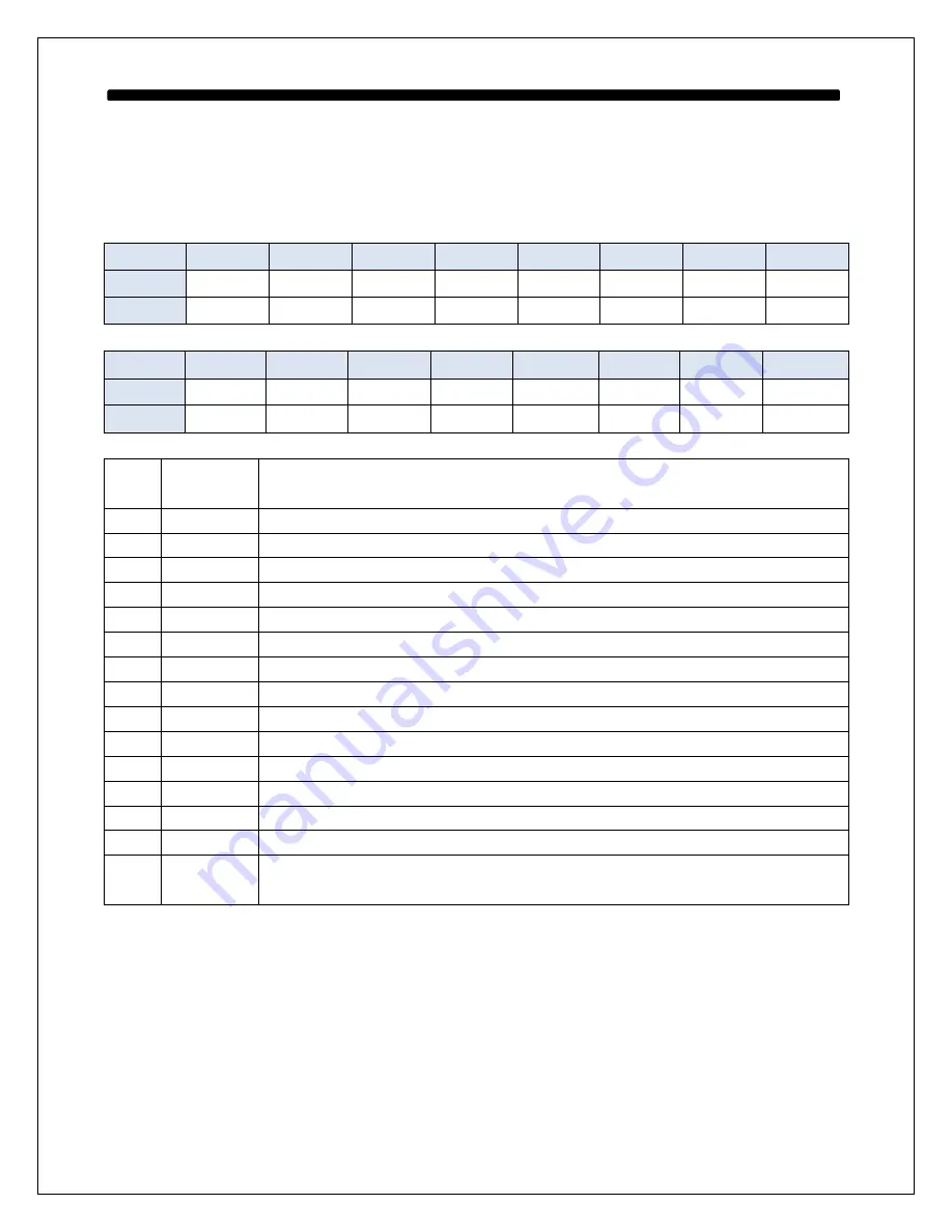
Main Output Control Latches (R/W) – 0x2400-0000
BIT
15
14
13
12
11
10
9
8
FIELD
TEST
EECOPY
“K3”
LED2
LED1
RT2ENA RT1ENA BCENA
RESET
0
0
0
1
0
0
0
0
BIT
7
6
5
4
3
2
1
0
FIELD
MR
MTRUN TXINHA TXINHB RAMDEC
TP31
ACKIRQ BCTRING
RESET
0
0
1
1
0
0
0
0
DO
BCTRIG
HI-6130 input. Rising edge triggers the BC to execute next Opcode instruction.
Usually used to start BC transmissions.
D1
ACKIRQ
HI-6130 input.
D2
TP31
CPLD spare pin.
D3
RAMEDC
HI-6130 Error detection/correction input. Set Low for this program.
D4
TXINHB
HI-6130 Bus B inhibit input.
D5
TXINHA
HI-6130 Bus A inhibit input.
D6
MTRUN
HI-6130 MT enable input.
D7
/MR
HI-6130 Master Reset input.
D8
BCENA
HI-6130 BC enable input.
D9
RT1ENA
HI-6130 RT1 enable input.
D10
RT2ENA
HI-6130 RT2 enable input.
D11
/LED1
General purpose LED (LED10 on board). On (low) at power up.
D12
/LED2
General purpose LED (LED11 on board). Off (high) at power up.
D13
“K3”
Not used but brought out to a pad on the PCB from the CPLD.
D14
EECOPY
HI-6130 EECOPY input.
D15
TEST
HI-6130 TEST input. Must be set Low for normal operation. See data sheet for Test
Mode details.


