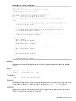
background image

Example 5

help cpuconfig

command

Shell> help cpuconfig

CPUCONFIG [cpu] [on | off]

cpu

Specifies which cpu to configure

on | off Specifies to configure or deconfigure a cpu

Notes:

1. Cpu status will not change until next boot

Examples:

* To deconfigure CPU 0
fs0:\> cpuconfig 0 off
CPU will be deconfigured on the next boot

* To display configuration status of cpus
fs0:\> cpuconfig
<CPU configuration data displayed>
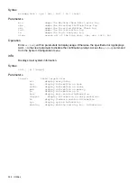
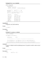
Example 6

help ioconfig

command

Shell> help ioconfig
Deconfigure or reconfigure IO components or settings

IOCONFIG [fast_init | wol [on | off]]

fast_init

Specifies device connection policy setting

wol

Specifies System Wake-On-LAN setting

on | off

Specifies to configure or deconfigure a feature or component

Note:

1. If fast_init is enabled, firmware will connect only the minimum set of

devices during boot.

This feature might cause boot failure; disable this

feature if failure occurs.

2. Any pending Wake-On-LAN request will not be cleared until reboot if

the setting is changed to disabled.

System will clear pending Wake-On-LAN requests each time the system
reboots if the setting is disabled.

Examples:

* To display the current settings

fs0:\> ioconfig
Fast initialization: Enabled
System Wake-On-LAN: Disabled

* To display the current device connection policy setting

fs0:\> ioconfig fast_init
Fast initialization: Enabled

* To disable fast initialization

fs0:\> ioconfig fast_init off
Fast initialization: Disabled

* To enable the System Wake-On-LAN setting

fs0:\> ioconfig wol on
System Wake-On-LAN: Enabled
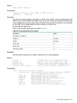
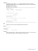
baud

Sets the baud rate and communication settings for a universal asynchronous receiver-transmitter
(UART).

320

Utilities

Summary of Contents for AB464-9003F

Page 1: ...HPE Integrity rx6600 Server User Service Guide Part Number AB464 9003F Published February 2016 Edition 12 ...

Page 2: ...r copying Consistent with FAR 12 211 and 12 212 Commercial Computer Software Computer Software Documentation and Technical Data for Commercial Items are licensed to the U S Government under vendor s standard commercial license Links to third party websites take you outside the Hewlett Packard Enterprise website Hewlett Packard Enterprise has no control over and is not responsible for information o...

Page 3: ...isk Drive LEDs 29 Hot Pluggable Disk Drive Slot Availability LEDs 31 DVD Drive 31 Diagnostic Panel 31 Rear Panel 32 iLO 2 MP 33 iLO 2 MP Reset Button 34 Core I O Board Ports 34 iLO 2 MP Status and LAN LEDs 35 System LAN 35 Power Supply 36 Rear Panel UID LED and Button 37 PCI PCI X PCIe Card Slot 37 2 System Specifications 38 Server Specifications 38 Dimensions and Weight 38 Grounding 39 Electrical...

Page 4: ...rrier Assembly 55 Removing the Memory Carrier Assembly 55 Replacing the Memory Carrier Assembly 56 Installing System Memory DIMMs 57 Memory Installation Conventions 59 Supported DIMM Sizes and Memory Configurations 59 Memory Load Order 60 Memory Loading Rules and Guidelines 61 Installing Memory 62 Removing and Replacing the Processor Board Assembly 64 Removing the Processor Board Assembly 65 Repla...

Page 5: ...f the Server Using the iLO 2 MP 89 Powering Off the Server Manually 89 Powering On the Server 89 Powering On the Server Using the iLO 2 MP 89 Powering On the Server Manually 90 Core I O Card Configuration 90 Integrated RAID 90 Integrated Mirror 90 Global Hot Spare 90 HPE 8 Internal Port SAS HBA SAS Controller 90 MPTUTIL Utility 91 Flashing Firmware on First Controller 91 Flashing BIOS and EFI Driv...

Page 6: ...nager 120 Booting HP UX From the EFI Shell 121 Booting HP UX in Single User Mode 122 Booting HP UX in LVM Maintenance Mode 123 Shutting Down HP UX 123 Booting and Shutting Down HPE OpenVMS 124 Adding HPE OpenVMS to the Boot Options List 124 Booting HPE OpenVMS 125 Booting HPE OpenVMS from the EFI Boot Manager 125 Booting HPE OpenVMS from the EFI Shell 125 Shutting Down HPE OpenVMS 126 Booting and ...

Page 7: ...are Monitors 148 Errors and Reading Error Logs 148 Event Log Definitions 148 Using Event Logs 148 iLO 2 MP Event Logs 149 System Event Log SEL Review 149 Supported Configurations 151 System Block Diagram 151 System Build Up Troubleshooting Procedure 153 CPU Memory SBA 155 Troubleshooting the CPU 155 IPF Processor Load Order 155 Processor Module Behaviors 155 Customer Messaging Policy 156 Troublesh...

Page 8: ...e Top Cover 178 Removing the Top Cover 178 Replacing the Top Cover 179 Removing and Replacing the Memory Carrier Assembly Cover 179 Removing the Memory Carrier Assembly Cover 179 Replacing the Memory Carrier Assembly Cover 180 Removing and Replacing a Hot Swappable Chassis Fan Unit 180 Removing an Internal Hot Swappable Chassis Fan Unit 181 Replacing an Internal Hot Swappable Chassis Fan Unit 182 ...

Page 9: ...Replacing the Processor Board Assembly 216 Removing and Replacing a Dual Core Processor 217 Processor Load Order 217 Required Tools 218 Removing a Dual Core Processor 218 Installing a Dual Core Processor 222 Removing and Replacing the I O Board Assembly 224 Removing the I O Board Assembly 224 Replacing the I O Board Assembly 226 Removing and Replacing the System Battery 228 Removing the System Bat...

Page 10: ...ustomer Self Repair 257 Parts List 258 B Upgrades 262 I O Backplane Upgrade 262 I O Backplane Upgrade Overview 262 Required Service Tools 263 Safety Information 263 I O Backplane Upgrade Procedure 264 Installing Core I O Cards 268 Installing the HPE Eight Internal Port SAS Host Bus Adapter 269 Installing the HPE Smart Array P600 270 Installing the HPE Smart Array P400 271 Completing the Adapter In...

Page 11: ... Smart Array P400 P600 and P800 Controllers 305 Quick Installation Procedure 305 Connecting External Storage 306 SAS Cable Part Numbers 306 SAUPDATE Utility 306 Syntax 307 Commands 307 List 307 UPDATE 307 UPDATE all 308 HELP or 309 Error Messages 309 EBSU Utility 309 Configuring the Array 312 Comparing the Utilities 312 ORCA Utility 313 Creating a Logical Drive Using ORCA 314 ACU Utility 314 D Uti...

Page 12: ...ifying SCSI Parameters 335 Using the SCSI Setup Utility 335 Using the Boot Option Maintenance Menu 341 Paths 341 Boot From a File 342 Add a Boot Option 342 Delete Boot Option s 343 Change Boot Order 343 Manage BootNext Setting 344 Set Auto Boot TimeOut 344 Select Active Console Output Devices 345 Select Active Console Input Devices 345 Select Active Standard Error Devices 346 Using the System Conf...

Page 13: ...Turkey RoHS material content declaration 349 Ukraine RoHS material content declaration 349 Index 350 Contents 13 ...

Page 14: ...Integrity_Servers docs Intended Audience This document is intended to provide technical product and support information for authorized service providers customer system administrators and Hewlett Packard Enterprise support personnel New and Changed Information in This Edition Updated behaviour of Hot Pluggable disk drive LEDs in RAID and Standalone HBA mode Publishing History Table 1 lists the pub...

Page 15: ...ed on the server Troubleshooting page 134 Use this chapter to help troubleshoot and diagnose server problems Removing and Replacing Server Components page 174 Use this chapter to learn how to remove and replace server components Customer Replaceable Units Information page 257 This appendix lists the field replaceable units FRU Upgrades page 262 Use this appendix to learn upgrade procedures Core I ...

Page 16: ...d UCIO are not hot pluggable Hot plug PCI PCI X PCIe hot pluggable operations enable you to add or remove a PCI PCI X PCIe card while the server is powered on Each slot is physically separated with a divider that contains a card extraction mechanism and a mechanical retention latch MRL Slots 3 10 on the 10 slot PCI PCI X IOBP and slots 5 10 on the 10 slot PCI PCI X PCIe IOBP support Hewlett Packar...

Page 17: ...Private Fast core slots PCI X mode1 and 1 Private Slow core UCIO slot PCI 32 bit 33 MHz The eight Public slots are further subdivided into three speed bandwidth configurations Four PDHP Public Dual Hot plug which operate at 64 bit 66 MHz PCI X Two PSHP SDR Public Single Hot plug Single Data Rate operating at 64 bit 133 MHz PCI X Two PSHP DDR Public Single Hot plug Double Data Rate at 64 bit 266 MH...

Page 18: ...Speed PCI X Public 133 MHz 64 5 2 2 3 Dual Bandwidth 6 Y General PCI X Public 66 MHz 64 6 5 9 7 8 Y General PCI X Public 66 MHz 64 7 1 1 9 10 N UCIO Private 33 MHz 32 0 0 0 PCI PCI X PCIe IOBP On the 10 slot PCI PCI X PCIe IOBP there are a total of eight Public slots four PCI X mode 1 and four PCIe two Private Fast core slots PCI PCI X mode 1 64 bit 66 MHz and one Private Slow core UCIO slot PCI 3...

Page 19: ...tting See info page 326 To enable PCIe MPS optimization use the ioconfig mps_optimize command See ioconfig page 324 For non PCIe systems ioconfig and info io will not display the MPS optimization policy setting The Set PCIe MPS Optimization boot manager menu also will not be displayed Running the ioconfig mps_optimize on off command from a non PCIe system the following output will be displayed She...

Page 20: ...e seated on memory boards that are enclosed in an extractable memory carrier assembly Figure 3 Memory Carrier Assembly The memory boards plug directly into sockets on the processor board when the memory carrier assembly is fully seated The server supports the following DIMM sizes 512 MB 1 GB 2 GB 4 GB 8 GB Table 4 lists the memory carrier configurations the minimum and maximum memory for each conf...

Page 21: ...d or pair Firmware Updates HPE Integrity servers require system firmware version 03 01 or later to support the following Memory Add On products AH350A 2 GB DDR2 Memory Pair 2 x 1 GB DIMMs AB564A 4 GB DDR2 Memory Pair 4 x 1 GB DIMMs AB565A 8 GB DDR2 Memory Pair 4 x 2 GB DIMMs AB566A 16 GB DDR2 Memory Pair 4 x 4 GB DIMMs supported in HPE Integrity rx3600 servers with 8 DIMM memory carrier only Befor...

Page 22: ...temperature condition Table 5 Fan Events Action Event All rotors to maximum speed 1 Server chassis top cover removed All remaining rotors to maximum speed One fan rotor fails or is too slow All remaining rotors to maximum speed and hard shut down after two minutes of continuous failure Two or more fan motors fail or are too slow All remaining rotors to maximum speed and hard shut down after two mi...

Page 23: ...splay pca and held in contact mode by the top cover Power supplies each with its own pair of fans running at full speed and its own virtual health sensor 0x40 0x41 Fan units 1 through 6 consisting of 2 individual fans rotors 0xe0 to 0xe9 Power The server power subsystem is designed to provide high availability with 1 1 power supply redundancy Figure 5 page 24 is a block diagram of the power subsys...

Page 24: ...be sent to the system by pulsing ACPI_PWR_BTN_L when the ACPI bits are set to note the OS has shut down the BMC will perform a hard power down If the system has not booted to an OS or if a long 5 second button press is detected the system will do an immediate hard power off System Power State Management The system power may be controlled from the Power button an IPMI Chassis command Wake On LAN lo...

Page 25: ...he chassis Service the display board from the top of the chassis The front display panel consists of the system status LEDs and a power switch Use the front display panel to determine the power status of the server and monitor the server as it progresses through the boot cycle Use the various LED states to assist with troubleshooting system problems A slimline DVD drive or optional DVD RW drive is...

Page 26: ... Slot 2 Slot 1 1 Slot 10 Slots 1 and 2 2 Slot 2 Slots 1 and 3 2 Slot 2 Slot 3 1 Slot 2 Slots 3 and 4 2 Firmware Firmware consists of many individually linked binary images that are bound together by a single framework at run time Internally the firmware employs a software database called a device tree to represent the structure of the hardware platform and to provide a means of associating softwar...

Page 27: ...d EFI Shell to support Hewlett Packard Enterprise value added functionality Event IDs for Errors and Events The system firmware generates event IDs for errors events and forward progress to the iLO 2 MP through common shared memory The iLO 2 MP interprets and stores event IDs Reviewing these events helps you diagnose and troubleshoot problems with the server Controls Ports and LEDs This section pr...

Page 28: ...ellow UID button is not activated Off Helps locate a particular server within a rack of UID Button UID button is activated Blue servers You can remotely activate this button using various system utilities 1 Resets the system irrecoverably halts all Init Button system processing and I O activity and restarts the server System is off Off Provides information about the system status System Health LED...

Page 29: ...he external health LED is lit System health is degraded Flashing amber the corresponding failed component LED illuminates System health is critical Flashing red 1 There is an additional UID LED and button located on the rear panel of the server Both UID LEDs illuminate when you activate either the front or rear UID buttons Figure 8 shows the front control panel LEDs Figure 8 Front Control Panel LE...

Page 30: ...ilding Off Flashing green at constant 1 Hz 1 The Drive Status LED is blue when you use various software utilities such as online diagnostics and SAS drive configuration tools Table 9 lists the hot pluggable disk drive LEDs and states in Standalone HBA mode Table 9 Behaviour of Hot Pluggable Disk Drive LEDs in Standalone HBA mode Disk Drive State Status LED Activity LED Offline or not configured Of...

Page 31: ...e Disk Drive Slot Availability LEDs DVD Drive The server has one DVD drive or one DVD RW drive This device has one activity LED Figure 11 DVD Drive Diagnostic Panel The diagnostics panel provides a single location to view the LEDs that provide location information for internal system components that have a detectable failure The LEDs illuminate solid amber only when a failure occurs and otherwise ...

Page 32: ...n ports I O ports AC power connectors and the locator LED button LEDs located on the rear panel of the server indicate the operational status of the following components iLO 2 MP System LAN Power supply PCI PCI X PCIe slots Figure 13 shows the rear panel control port and LED locations 32 Overview ...

Page 33: ...hat enables local and remote management of the server As long as AC power is present whether at standby or full power the iLO 2 MP can function Figure 14 shows the controls ports and LEDs on the core I O board The figure is oriented vertically to match the orientation of the core I O board Controls Ports and LEDs 33 ...

Page 34: ...s you to reset the iLO 2 MP and optionally reset the user specific values to factory default values To soft reset the iLO 2 MP press the button momentarily then release it To soft reset the iLO 2 MP and return user specific values to factory default values press the button for more than four seconds then release it The following values are reset to factory default values Serial terminal baud rate ...

Page 35: ...ed Off Operational and functional Flashing green iLO 2 MP Heartbeat Operational and functional Flashing green BMC Heartbeat Activity Blinking green Link Status Link with no activity Solid green No link Off 100 Mb link Solid amber Link Speed 10 Mb link Off 1 The LED is solid amber when AC power is first applied It remains solid amber for a few seconds until the iLO 2 MP completes its self test the ...

Page 36: ...chassis to achieve the standby power state To bring the server to full power plug the power cord into the appropriate receptacle and either activate the power using the iLO 2 MP PC command or push the Power button To bring the server to the off state unplug the power cords Table 13 lists the power supply LED states Table 13 Power Supply LED Power Supply Condition Power Supply LED No AC power Off A...

Page 37: ...when you activate either of the front or rear UID buttons PCI PCI X PCIe Card Slot The server has eight public hot pluggable PCI PCI X PCIe slots and two private core I O slots Each slot has an attention LED that serves two purposes Figure 13 It indicates a potential problem with the slot that requires immediate attention Additionally the LED can function as a locator used to identify a particular...

Page 38: ...6 MHz Two PCI X slots 133 MHz Two PCI X slots 133 MHz Four PCIe x8 Two PCI X2 slots 266 MHz SAS core I O options Eight port SAS core I O card PCI X Eight port SAS core I O card PCI X Eight port SAS core I O card with RAID PCI X Eight port SAS core I O card with RAID PCI X Eight port SAS core I O card with RAID PCIe Eight port SAS core I O card with RAID able to connect to external storage PCIe Two...

Page 39: ...ctor must be green with yellow stripes The earthing conductor is to be connected from the unit to the building installation earth or if supplied by a separately derived system at the supply transformer or motor generator set grounding point Electrical Specifications This section provides electrical specifications for the server System Power Specifications Available power output is the maximum dc p...

Page 40: ...e is an undetected short circuit somewhere When you use the front panel Power button to turn off the server power consumption falls below the low power consumption but doesn t reach zero To reach zero power consumption in off mode either unplug the server or use a power block with a switch Power Consumption and Cooling Table 18 lists additional component power consumption Table 18 Additional Compo...

Page 41: ...lly initiates a system shutdown via interruption of internal DC power the OS halts immediately 3 Typical configuration at room temperature 25 C 4 Single processor one to two SCSI hard disk drives and less than 8GB of memory 5 Dual processor three SCSI hard disk drives and more than 8GB of memory Table 20 Physical and Environmental Specifications Overall System Dimensions W X D X H Weight Condition...

Page 42: ...x 1 6G 24M CPUs 48x 4GB DDRII DIMM memory 16x SAS Hard Drives 8x PCI PCI X PCIe added to public I O cards Maximum Configuration Front to Rear F R Half loaded configuration 2x Itanium 1 4G 12M or 1 6G 18M or 1 6G 24M CPUs 24x 4GB DDRII DIMM memory 8x SAS Hard Drives 4x PCI PCI X PCIe added to public I O cards Typical Configuration 1 Derate maximum dry bulb temperature 1oC 300 m above 900 m 2 m 3 hr...

Page 43: ...ess you are removing or installing a hot swappable or hot pluggable component Voltages are present at various locations within the server whenever an AC power source is connected This voltage is present even when the main power switch is turned off Failure to observe this warning can result in personal injury or damage to equipment Do not wear loose clothing that can snag or catch on the server or...

Page 44: ...on server electrical physical space and environmental requirements see the Integrity rx6600 Site Preparation Guide Inspecting the Shipping Containers for Damage Hewlett Packard Enterprise shipping containers protect their contents under normal shipping conditions After the equipment arrives carefully inspect each carton for signs of shipping damage Shipping damage constitutes moderate to severe da...

Page 45: ...ired to elevate the server and enable the forks of the lifter to be inserted under the server 4 Insert the lifter forks under the server 5 Roll the lifter forward carefully until it is positioned against the side of the server 6 Raise the server slowly off the pallet until it clears the pallet cushions 7 Roll the lifter and server away from the pallet Do not raise the server any higher than necess...

Page 46: ...placing the Top Cover NOTE Always replace the memory carrier assembly cover before replacing the top cover To replace the top cover follow these steps 1 Ensure the memory carrier assembly cover is in place 2 Ensure the cover release lever is in the unlocked position Figure 17 3 Align the tabs of the top cover with the corresponding slots in the chassis Insert the tabs into the slots 4 Slide the co...

Page 47: ...ssis Figure 17 3 Slide the memory carrier assembly cover toward the left side of the server to free it from the center of the chassis Lift the cover off the chassis Figure 18 Figure 18 Removing and Replacing the Memory Carrier Assembly Cover Replacing the Memory Carrier Assembly Cover To replace the memory carrier assembly cover follow these steps 1 Position the cover onto the opening above the me...

Page 48: ...m of one power supply installed in either slot P0 or slot P1 You can install a second optional hot swappable power supply to provide 1 1 capability The left side viewed from the rear of the chassis hot swappable power supply is identified as P0 and the second hot swappable power supply is identified as P1 Figure 19 CAUTION When a second power supply is not used the empty power supply slot must rem...

Page 49: ...drive IMPORTANT For cooling purposes always leave disk drive fillers in slots that do not contain a disk drive Removing a Hot Swappable Disk Drive Filler To remove a hot swappable disk drive filler follow these steps 1 Squeeze the tabs on the front of the filler to release it from the slot in the drive bay 2 Pull gently until the filler slides out of the chassis Installing Additional Components 49...

Page 50: ...re you can safely move SAS devices downwards as a block If you have bays 6 7 and 8 occupied you can move them down to bays 1 2 and 3 without having the hardware paths change during a cold install or recovery while the system is shut down but you must move the disks in order and you cannot rearrange them For example you can move bay 6 to 1 7 to 2 and 8 to 3 After doing this you can safely populate ...

Page 51: ...teps 1 Use Figure 22 to determine the next available disk drive installation slot 2 Remove the disk drive filler if required See Removing a Hot Swappable Disk Drive Filler page 49 NOTE Save the disk drive filler for future use For cooling purposes always place disk drive fillers in slots that do not contain a disk drive 3 Insert the hot pluggable disk drive into the slot guides and slide the drive...

Page 52: ...ntification and card divider locations NOTE Slots one through eight are full length slots nine and ten are short length Figure 23 PCI PCI X Slot Identification and Card Divider Locations 9 Slot 9 5 Slot 5 1 Slot 1 2 Slot 2 10 Slot 10 6 Slot 6 7 Slot 7 3 Slot 3 11 Core I O Board Slot 52 Installing the System ...

Page 53: ... current bus configuration it only runs at the slower bus mode and frequency of the current bus configuration The following are common configuration scenarios for cards that use shared slots These examples also apply to slots 9 and 10 because they are shared both use a common bus 1 If there is a PCI X 66 MHz card in slot 7 and you hot plug insert a PCI 33 MHz card into slot 8 the operation fails T...

Page 54: ...tible 2 New card running at PCI X 66 Incompatible bus 4 Incompatible frequency 3 PCI X 66 MHz 1 The conditions described in this table apply only to shared slots 7 8 9 and 10 Slots 1 2 3 4 5 and 6 are not shared slots 2 Compatible card is accepted and runs at the frequency shown 3 Incompatible frequency card does not work The new card does not initialize and powers down due to frequency mismatch 4...

Page 55: ...oard 24 DIMM memory carrier configuration 1 2 X 24 DIMM memory boards 48 DIMM memory carrier configuration 2 CAUTION Observe all ESD safety precautions before attempting this procedure Failure to follow ESD safety precautions can result in damage to the server Removing the Memory Carrier Assembly WARNING Ensure that the system is powered off and all power sources have been disconnected from the se...

Page 56: ...eplace the memory carrier into the chassis Figure 24 Removing and Replacing the Memory Carrier Assembly Replacing the Memory Carrier Assembly CAUTION Ensure the processor board assembly is fully seated before you replace the memory carrier assembly The processor board assembly access door must be flush with the front bezel To replace the memory carrier assembly follow these steps 1 Ensure that the...

Page 57: ...nd Replacing the Memory Carrier Assembly Cover page 47 Installing System Memory DIMMs System memory DIMMs are located on a pair of memory boards inside the memory carrier assembly WARNING Ensure that the system is powered off and all power sources have been disconnected from the server prior to performing this procedure Voltages are present at various locations within the server whenever an AC pow...

Page 58: ...Figure 25 Memory Carrier Assembly Figure 26 shows the memory carrier with the side cover open 58 Installing the System ...

Page 59: ...MM Sizes and Memory Configurations The standard server configuration includes a 48 DIMM memory carrier which contains one or two 24 DIMM memory boards System DIMMs seat onto the memory boards The minimum server configuration requires at least one memory quad or group of four DIMMs The following are the supported DIMM sizes for the server 512 MB 1 GB 2 GB 4 GB 8 GB Table 24 lists the supported memo...

Page 60: ...Failure to observe these cautions results in system degradation or failure Do not mix DIMM sizes or types within a quad Load DIMM quads in order of size from largest to smallest For example if you have a quad of 2 GB DIMMs and a quad of 1 GB DIMMs install the quad of 2 GB DIMMs first 24 DIMM Memory Carrier Load Order For a single 24 DIMM memory board configuration load DIMMs in order from quad 0 t...

Page 61: ...est For example install all 2 GB quads before 1 GB or smaller quads and install all 1 GB quads before 512 MB quads Side 0 must have equal or greater memory capacity than side 1 Install DIMM quads based on the following rules Load quads into either side of the memory carrier in order starting with quad 0 and ending with quad 5 1 2 Install the first quad in side 0 quad 0 3 Install the second quad in...

Page 62: ...s 4 2 GB DIMMs 3 1A 1B 1C 1D 1 1 GB DIMMs 6 1 GB DIMMs 5 2A 2B 2C 2D 2 1 GB DIMMs 8 1 GB DIMMs 7 3A 3B 3C 3D 3 512 MB 10 512 MB 9 4A 4B 4C 4D 4 512 MB 12 512 MB 11 5A 5B 5C 5D 5 Example 2 1 GB DIMMs 2 2 GB DIMMs 1 0A 0B 0C 0D 0 1 GB DIMMs 3 1 GB DIMMs 4 1A 1B 1C 1D 1 512 MB 5 512 MB 7 2A 2B 2C 2D 2 512 MB 6 512 MB 9 3A 3B 3C 3D 3 512 MB 8 4A 4B 4C 4D 4 512 MB 10 5A 5B 5C 5D 5 Example 3 512 MB 2 2 ...

Page 63: ...Complete the following memory installation prerequisite tasks before installing the memory a Determine the DIMM load order for the 48 DIMM memory carrier For more information see Memory Load Order page 60 b Use Figure 27 to determine the DIMM slots to populate c Read understand and follow the general guidelines to install memory in the server See Memory Loading Rules and Guidelines page 61 4 Lay t...

Page 64: ...ert the tabs Figure 25 into the slots on both sides of the extraction handle release button until the side cover snaps into place NOTE To install DIMMs into slots on the other side of the memory carrier turn the carrier over to the opposite side side 0 or side 1 and repeat the installation procedure 8 Replace the memory carrier assembly and latch the top cover release lever See Removing and Replac...

Page 65: ... the memory carrier assembly cover See Removing and Replacing the Top Cover page 45 You do not need to fully remove the top cover to service this component however the top cover release lever must be open 2 Remove the memory carrier assembly See Removing and Replacing the Memory Carrier Assembly Cover page 47 NOTE You must remove the memory carrier because it attaches directly to the processor boa...

Page 66: ...r assembly See Removing and Replacing the Memory Carrier Assembly page 55 6 Replace the memory carrier assembly cover and latch the top cover release lever closed See Removing and Replacing the Memory Carrier Assembly Cover page 47 Installing a Dual Core Processor The server uses dual core processors Each processor contains two cores that function as separate processors Dual core processors double...

Page 67: ...o or three in the Integrity rx6600 server install them in the designated locations on the processor board The slots on the processor board are labeled Module 0 Module 1 Module 2 and Module 3 The Module 0 and Module 1 slots are located on the top of the processor board assembly and the Module 2 and Module 3 slots are located on the underside of the processor board assembly IMPORTANT Use the supplie...

Page 68: ...nlock the socket CAUTION Attempting to turn the locking mechanism more than 180 degrees can severely damage the socket 9 Remove any protective packaging from the processor NOTE Protective covers are installed to protect connector pins Save the covers for future use 10 Inspect the processor pins and verify that the pins are not bent 11 Align the alignment holes on the processor with the alignment p...

Page 69: ... and Replacing the Processor Board Assembly page 64 16 Replace the memory carrier assembly See Removing and Replacing the Memory Carrier Assembly page 55 17 Replace the memory carrier assembly cover and latch the top cover release lever closed See Removing and Replacing the Memory Carrier Assembly Cover page 47 Figure 30 Installing a Dual Core Processor on the Processor Board Figure 31 shows the p...

Page 70: ...Figure 31 Processor Power Cable Figure 32 shows the processor socket lock unlock mechanism and alignment post locations without a processor installed 70 Installing the System ...

Page 71: ...e 32 Processor Alignment Posts and Lock Unlock Mechanism Figure 33 shows the processor lock unlock mechanism location and the alignment holes with the processor installed Installing Additional Components 71 ...

Page 72: ...ing the Server into a Rack The following information describes how to install the server into a Hewlett Packard Enterprise rack or an approved non Hewlett Packard Enterprise rack Hewlett Packard Enterprise Rack Hewlett Packard Enterprise servers that are installed into racks are shipped with equipment mounting slides An installation guide comes with each set of slides HPE 3 7U Quick Deploy 72 Inst...

Page 73: ...the menu then select Mounting in non HP racks Installing the Server into a Pedestal Mount The server ships with a pedestal mount if you order the rackless configuration option The pedestal mount is packaged in a separate carton that is attached to the server carton To change the server from a rack mount to a rackless configuration you need a Server Rackless Mount Kit The rackless mount kit comes w...

Page 74: ...ated Power Cable Plugged Into Receptacle Power States No Yes No Yes Standby power Yes Yes Yes Yes Full power No No No No Off NOTE If the power restore feature is set to Always On through the iLO 2 MP PR command the server can automatically power on to the full power state Attaching the Hook and Loop Strap to the Bulk Power Supply and Power Cord CAUTION If you do not fasten the hook and loop strap ...

Page 75: ...nt intervals to ensure the server is in the standby power state INTERVAL ONE After you plug the power cord into the server the BPS flashes amber and an amber light is present on the hard disk drives INTERVAL TWO Approximately 30 seconds later the BPS flashes green and the amber light is still present on the hard disk drives Standby power is now on LAN The server has two LAN ports that can provide ...

Page 76: ...g tasks for the server hardware It controls power reset and Transfer of Control TOC capabilities provides console access displays and records system events and displays detailed information about internal subsystems The iLO 2 MP is available whenever the system is connected to a power source even if the server main power switch is turned off NOTE For more information on iLO 2 see the HPE Integrity...

Page 77: ...efault user name and password Log on to the iLO 2 MP 3 Change the default user name and password on the administrator account to your predefined selections Change default user name and password 4 Set up the user accounts if using the local accounts feature Set up user accounts 5 Set up the security access settings Set up security access 6 Access the host console using method of choice Access the h...

Page 78: ...ration method and assign an IP address if necessary Determining the Physical iLO 2 MP Access Method Before you can access the iLO 2 MP you must first determine the correct physical connection method The iLO 2 MP has a separate LAN port from the system LAN port It requires a separate LAN drop IP address and networking information from that of the port used by the operating system Figure 37 78 Insta...

Page 79: ...s to the host console Table 30 Physical Connection Matrix Required Connection Components Connection Method RS 232 serial port 1 Host console 2 RS 232 serial port DB 9F to DB 9F cable 3 Emulation terminal device for example a PC laptop or ASCII terminal 10 100 LAN cable LAN port Determining the iLO 2 MP LAN Configuration Method To access the iLO 2 MP through the iLO 2 MP LAN the iLO 2 MP must acqui...

Page 80: ...NS DHCP automatically configures all DHCP enabled servers with IP addresses subnet masks and gateway addresses All Integrity entry class servers with the iLO 2 MP are shipped from the factory with DHCP enabled Hewlett Packard Enterprise recommends using the DHCP and DNS method to simplify access to the iLO 2 MP NOTE You can use ARP Ping regardless of the status of DHCP unless an IP address has eve...

Page 81: ...P Once an IP address is assigned using DHCP ARP Ping is permanently disabled Some DHCP server options can cause the apparent issuance of ARP Ping to the iLO 2 MP which will negate the DHCP DDNS method The Address Resolution Protocol ARP and Packet Internet Grouper Ping utility uses ARP packets to ping or discover a device on the local network segment The IP address you assign to the server must us...

Page 82: ... server 4 Open a DOS window on the PC 5 At the DOS prompt enter arp s to assign the IP address to the iLO MAC address Syntax arp s IP address you want to assign to the iLO MAC address iLO 2 MAC address Example from Windows arp s 192 0 2 1 00 00 0c 07 ac 00 6 At the DOS prompt enter ping followed by the IP address to verify that the iLO 2 MP LAN port is configured with the appropriate IP address Th...

Page 83: ...software options 2 Determine the required connection components and the ports used to connect the server to the console device 3 Connect the cables from the appropriate ports to the server 4 Start the emulation software on the console device 5 Log in to the iLO 2 MP See Logging In to the iLO 2 MP page 83 6 At the MP Main Menu enter CM and press Enter to select command mode 7 At the command mode pr...

Page 84: ...u and the iLO 2 MP prompt MP press Ctrl B Additional Setup This section provides additional information to setup the iLO 2 MP Modifying User Accounts and Default Password The iLO 2 MP comes preconfigured with default factory settings including a default user account and password The two default user accounts on initial login are All Rights Administrator level user login Admin password Admin Consol...

Page 85: ...to the iLO 2 MP Change the default user name and password See Modifying User Accounts and Default Password page 84 CAUTION When DHCP is enabled the system is vulnerable to security risks because anyone can access the iLO 2 MP until you change the default user name and password Hewlett Packard Enterprise strongly recommends you assign user groups and rights before proceeding Create local accounts Y...

Page 86: ...ract with the iLO 2 MP through the web GUI follow these steps 1 Open a web browser and enter the host name or the IP address for the iLO 2 MP 2 Log in using your user account name and password at the login page Figure 38 Figure 38 Web Login Page 3 Click Sign In The Status Summary page Figure 39 displays after login Figure 39 Status Summary Page 86 Installing the System ...

Page 87: ... to mirrored redirected console mode All mirrored data is displayed 3 To return to the iLO 2 MP command interface press Ctrl B or Esc and Accessing the Host Console With vKVM Integrated Remote Console For information on how to access the host console using the vKVM feature through the Integrated Remote Console IRC see the Integrity iLO 2 Operations Guide Accessing the Host Console with the SMASH S...

Page 88: ...for powering off and powering on the server For more information see the operating system documentation Server Power Button Figure 40 shows the server Power button Figure 40 Server Power Button Power States The server has three power states Standby power Plug the power cord into the appropriate receptacle on the rear of the chassis the front panel Power button is not turned on Full power Full powe...

Page 89: ...and enter YES when prompted to confirm the action IMPORTANT The main dc voltage is now removed from the system however AC voltage for standby power is still present in the server 6 Unplug all power cables from the receptacles on the rear panel of the server Powering Off the Server Manually To manually power off the server follow these steps 1 Gracefully shut down the operating system 2 Press the P...

Page 90: ...he mptutil command To configure and maintain the IR functionality of the SAS controller on the Integrity server use the drvcfg and cfggen EFI commands If you are scripting multiple devices use thecfggencommand Integrated Mirror The advantage of an IM is there is always a mirrored copy of the data An IM provides data protection for the system boot volume to safeguard critical information such as th...

Page 91: ...ne the current version of the firmware follow these steps a At the EFI Shell enter mptutil from the directory that contains mptutil efi The following example indicates that the EFI Serial Attached SCSI card utility version is 1 01 12 00 fs0 EFI HP TOOLS NETWORK mptutil MPTUTIL 1 01 12 00 Vendor Device Choice ID ID Bus Device 0 1000h 0054h 14h 01h LSI Logic SAS1068 Host Adapter 1 Refresh b Press En...

Page 92: ...set occurs If you exit the utility and reenter it the version string is updated Question This image does not contain a valid nvdata when I try to flash the firmware why Answer You are expected to concatenate a proper nvdata image on to the firmware mptutil keeps you from flashing an image without one To concatenate nvdata and firmware you need to run the mptutil o d 64it__l fw sas106x dat output f...

Page 93: ...n the cursor Change Item Items with values in brackets are modifiable Numeric keypad and numeric keypad minus update a modifiable field to its next relative value Esc Abort Exit Escape aborts the current context operation and or exits the current screen User confirmation is solicited as required if changes have been made by user If you are using a serial console pressing Esc causes a delay of seve...

Page 94: ...cimal PCI Dev Indicates the PCI Device assigned by the system BIOS to an adapter range 0x00 0x1F 0 31 decimal PCI Fnc Indicates the PCI Function assigned by the system BIOS to an adapter range 0x00 0x7 0 7 decimal FW Revision Displays the Fusion MPT firmware version and type IR or IT Status Indicates whether the adapter is or is not eligible for software control enabled disabled or error Enabled I...

Page 95: ... x xx xx xx yy where x xx xx xx refers to the FW version and yy refers to the type The currently supported type is IR l SAS Address Displays the SAS Address assigned to this adapter FW Revision Displays the Fusion MPT firmware version and type IR or IT Status Indicates whether an adapter is eligible for configuration utility software control or is reserved for control by other software Enabled Dis...

Page 96: ...ID Properties Screens There are four screens within RAID properties To access the screens select RAID Properties from the Adapter Properties screen The Select New Array Type screen displays Figure 43 Select New Array Type Screen Select New Array Type Screen The Select New Array Type screen enables you to view an existing array or create an Integrated Mirror array of two disks plus an optional hot ...

Page 97: ...sed as a hot spare for the IM array if No the device is not used as a hot spare for the IM array Only one hot spare per IM array is permitted A hot spare is not required in an IM You can specify a hot spare at array creation or any time after creation provided the array is made up of five disks or fewer This field is grayed out under the following conditions The device does not meet the minimum re...

Page 98: ...rent array configuration To access the View Array screen press Enter on the View Existing Array field from the Select New Array Type screen You can perform the following actions on the View Array screen To view the next array press N To create a new array press C Array Displays the number of this array Identifier Displays the identifier of this array Type Displays the RAID type Scan Order Displays...

Page 99: ...Primary Disk is the primary disk for a 2 disk mirror and is OK Secondary Disk is the secondary disk for a 2 disk mirror and is OK Wrg Type Device is not compatible for use as part of an IM array Too Small Disk is too small to mirror existing data Max Dsks Maximum of disks allowed for this type of Array reached and or Maximum of total IM disks on a controller reached No SMART Disk doesn t support S...

Page 100: ...e adapter s MPT firmware does not support the feature Non IR firmware is used IR is disabled The array is inactive Activate Array To perform an activation of an IM array press Enter on Activate Array The screen prompts you to ask if you want to perform this action Press Y for yes or N for no Delete Array To perform the deletion of the currently displayed IM array press Enter on Delete Array The sc...

Page 101: ...the EFI Shell prompt change to the CD drive shell fs0 Enter fs0 4 Change to the directory that containscfggen efi fs0 cd EFI HP TOOLS NETWORK Enter fs0 EFI HP TOOLS NETWORK From this directory use cfggen CFGGEN Operation cfggenis not case sensitive You can enter cfggen commands and parameters in uppercase lowercase or a mixture of the two Use the following conventions in the command descriptions T...

Page 102: ...he volume created noprompt Eliminates warnings and prompts Operation Once a disk has been added to an IM volume all of its storage capacity may or may not be used depending on drive capacity and volume capacity For example if you add a 36 GB disk drive to a volume that only uses 9 GB of capacity on each disk drive the remaining 27 GB of capacity on the disk drive is unusable The disk identified by...

Page 103: ...e sure the capacity of the hot spare disk is greater than or equal to the capacity of the smallest disk in the logical drive An easy way to verify this is to use the DISPLAY command CAUTION See Rules for creating IM volumes and hot spare disks page 102 Smart Array P400 P600 and P800 Controllers The following information is provided to assist you in configuring the Smart Array P400 P600 and P800 co...

Page 104: ...the cable to the SAS input connector of the external storage enclosure IMPORTANT Drives that are to be used in the same array must be of the same type either all SAS or all SATA Parallel SCSI drives cannot be used with this controller 5 Tighten the lock screws on the cable connector 6 Power on the enclosure 7 Power on the server SAS Cable Part Numbers If you require additional cables order them by...

Page 105: ...e version of the utility displays on the second line Smart Array Offline Firmware Update Utility Version 1 04 12 00 C Copyright 2004 Hewlett Packard Development Company L P Syntax saupdate operation parameters Commands You can use the following operations with saupdate LIST UPDATE UPDATE all HELP or List Use LIST to display all detected Smart Array controllers along with the active firmware versio...

Page 106: ...age to all the controllers to which the firmware image applies and updates the remaining controllers If an update operation fails for a controller the utility still updates the remaining controllers The example below shows the command to update all controllers for which the firmware image file applies The controllers for which the firmware image is not applicable are skipped In this example the Sm...

Page 107: ...CYBORG101 BIN Not Found When an invalid firmware or corrupted file is specified in the saupdate UPDATE command the example shows CYBORG101 BIN does not exist File CYBORG101 BIN invalid or corrupted EBSU Utility The EFI based Setup Utility EBSU provides an easy to use interface for flashing firmware partitioning the hard disk installing diagnostic tools configuring storage controllers and running o...

Page 108: ...er Figure 45 EBSU Main Menu 6 In the Maintain Firmware screen use the tab key to scroll down to the Device section 7 Use the down arrow key to scroll down to the Smart Array Controller item in the list 8 Press Enter to display detailed information about the device Figure 46 EBSU Maintain Firmware Screen 108 Installing the System ...

Page 109: ...0 Use the tab key to scroll down into the Device section and highlight the device name 11 Press Enter to select the device this puts an X inside the box on the left side of the device name 12 Use the tab key to move to the OK selection and press Enter The firmware update begins and proceeds automatically to completion Configuring the Array Hewlett Packard Enterprise provides two utilities for manu...

Page 110: ...rocedures for the ACU and ORCA utilities NOTE Yes in the appropriate column indicates that the feature or procedure is supported while No indicates that the feature or procedure is not supported Table 36 ACU and ORCA Supported Features and Procedures ORCA ACU Supported Features No Yes Uses a graphical interface No Yes Available in languages other than English No Yes Available on CE No Yes Uses a w...

Page 111: ...ves and the valid RAID options for the system 2 Use the Arrow keys Spacebar and Tab to navigate around the screen and set up the logical drive including an online spare drive if one is required NOTE You cannot use ORCA to configure one spare drive to be shared among several arrays Only ACU enables you to configure shared spare drives 3 Press Enter to accept the settings 4 Press F8 to confirm the s...

Page 112: ...event logs You can also observe the LED indicators on the front and rear of the server Error messages are displayed on local and remote consoles System history console event and history logs is available through the iLO 2 MP and is accessed through the console Offline troubleshooting programs are available on the resource CD that is shipped with the Hewlett Packard Enterprise server To troubleshoo...

Page 113: ...ower supply rear panels and take one of the following actions If the AC In indicators are lit power is available to the server If a fault indicator is lit reseat the power supply If the problem persists remove and reseat boards within the server If the problem persists replace the power supply or the power supply interface board If the AC Out indicators are lit power is available to the server cir...

Page 114: ...he DVD drive Hard Drive Problems Hard drive problems that occur during installation are usually due to rough handling The drive may not be correctly seated or may have been damaged in transit If you are experiencing hard drive problems follow these steps 1 Remove and reinsert the hard drive 2 Swap the hard drive with one from another slot or with a known good spare 3 Remove and reinstall the hard ...

Page 115: ...on The TPM is an optional security component which enhances security capabilities for the server if it is running the HP UX operating system The TPM is a security chip that is unique to the server It performs key security processes independent of other hardware components The TPM creates and stores additional encryption keys from the root key of the system The encryption keys created by the TPM en...

Page 116: ...efault c Enter secconfig to display a list of configurable security settings d Enter secconfig tpm on to enable the TPM 3 Reset the server 4 Boot the operating system 5 Restore the former TPM settings to the new TPM See the HP UX operating system documentation for more information 6 Back up the TPM security information See the HP UX operating system documentation for more information 116 Installin...

Page 117: ... might use only the primary console set via boot manager or conconfig command System Overview Boot Menu hp server BL870c HP UX Primary Boot 0 2 1 0 Serial USE7234MV8 Internal Bootable DVD EFI Shell Built in System Firmware 3 01 4739 iLO Virtual Media BMC Version 5 20 Core LAN Port 1 MP Version T 02 17 SuSE on fs0 Installed Memory 6144 MB HP UX 11 31 from SAS disk CPU Logical Boot Configuration Mod...

Page 118: ...ist Operating system utilities for managing the boot options list include the HP UX setboot command NOTE In some versions of EFI the Boot Configuration Menu is listed as the Boot Option Maintenance Menu To manage the boot options list for each server use the EFI Shell the EFI Boot Configuration Menu or operating system utilities At the EFI Shell the bcfg command supports listing and managing the b...

Page 119: ...s list see Adding HP UX to the Boot Options List page 119 To boot HP UX use the following procedures Booting HP UX From the EFI Boot Manager page 120 describes the standard ways to boot HP UX Typically this results in booting HP UX in multi user mode Booting HP UX in Single User Mode page 122 describes how to boot HP UX in single user mode Booting HP UX in LVM Maintenance Mode page 123 describes h...

Page 120: ...ription Add a new boot option to the position in the boot options list specified by The new boot option references file efi and is listed with the title specified by Description For example bcfg boot add1 EFI HPUX HPUX EFI HP UXi adds an HP UX 11i item as the first entry in the boot options list See the help bcfg command 4 Exit the console and iLO 2 MP interfaces if you are finished using them a T...

Page 121: ...em number can change each time it is mapped for example when the system boots or when the map r command is issued 4 When accessing the EFI System Partition for the desired boot device issue the HPUX command to initiate the HPUX EFI loader on the device you are accessing The full path for the loader is EFI HPUX HPUX EFI When initiated the loader references the EFI HPUX AUTO file and proceeds to boo...

Page 122: ... to initiate the EFI HPUX HPUX EFI loader on the device you are accessing 4 Boot to the HP UX Boot Loader prompt HPUX by pressing any key within the 10 seconds given for interrupting the HP UX boot process After you press a key the HPUX EFI interface the HP UX Boot Loader prompt HPUX launches For help using the HPUX EFI loader enter the help command To return to the EFI Shell enter exit fs0 hpux c...

Page 123: ...at the HPUX EFI interface the HP UX Boot Loader prompt HPUX 5 At the HPUX prompt enter the boot lm vmunix command to boot HP UX in LVM maintenance mode 6 Exit the console and iLO 2 MP interfaces when finished using them Press Control B to exit the system console and return to the MP Main Menu To exit the iLO 2 MP enter X at the MP Main Menu Shutting Down HP UX Use the shutdown command to shut down...

Page 124: ...t the Exit from the submenus until you return to the screen with the EFI Boot Manager heading c From the EFI Boot Manager menu select EFI Shell to access the EFI Shell environment 2 Access the EFI System Partition fsX where X is the file system number for the device from which you want to boot OpenVMS For example enter fs2 to access the EFI System Partition for the bootable file system number 2 Th...

Page 125: ...ic boot device and provides a specific set of boot options or arguments to use when booting the device 3 Press Enter to initiate booting using the selected boot option 4 Exit the console and iLO 2 MP interfaces when finished using them Press Control B to exit the system console and return to the MP Main Menu To exit the iLO 2 MP enter X at the MP Main Menu Booting HPE OpenVMS from the EFI Shell To...

Page 126: ...stem console Accessing the console through the iLO 2 MP enables you to maintain console access to the system after OpenVMS has shut down 3 At the OpenVMS DCL command element prompt issue the SYS SYSTEM SHUTDOWN command and specify the shutdown options in response to the prompts For example SYS SYSTEM SHUTDOWN SHUTDOWN Perform an Orderly System Shutdown on node RSNVMS How many minutes until final s...

Page 127: ...r the device from which you want to boot Microsoft Windows For example enter fs2 to access the EFI System Partition for the bootable file system number 2 The EFI Shell prompt changes to reflect the file system currently accessed The full path for the Microsoft Windows loader is efi microsoft winnt50 ia64ldr efi and it is on the device you are accessing NOTE You must only initiate this loader from ...

Page 128: ...bmenus until you return to the screen labeled EFI Boot Manager 2 Select an item from the boot options list Each item in the boot options list references a specific boot device and provides a specific set of boot options or arguments to be used when booting the device 3 Press Enter to initiate booting using the selected boot option 4 Once Windows begins loading wait for the Special Administration C...

Page 129: ... from the Command Line You can issue the shutdown command from a command prompt through the Special Administration Console SAC or from any other command line The Windows shutdown command includes the following options s Shuts down and powers off the system This is the equivalent of Start Shut Down Shut down To power on the system use the iLO 2 MP PC command r Shuts down and restarts the system Thi...

Page 130: ...y to the boot options list see Adding Linux to the Boot Options List page 130 To boot Linux on entry class Integrity servers use the following procedures See Booting the Red Hat Enterprise Linux Operating System page 131 See Booting the SuSE Linux Enterprise Server Operating System page 132 To shut down either Red Hat Enterprise Linux or SuSE Linux Enterprise Server see Shutting Down Linux page 13...

Page 131: ...xample bcfg boot add 1 EFI redhat elilo efi Red Hat Enterprise Linux adds a Red Hat Enterprise Linux item as the first entry in the boot options list Likewise bcfg boot add 1 efi SuSE elilo efi SLES 9 adds a SuSE Linux item as the first entry in the boot options list See the help bcfg command 4 Exit the console and iLO 2 MP interfaces if you are finished using them Press Control B to exit the syst...

Page 132: ...erating System You can boot the SuSE Linux Enterprise Server 9 operating system on Integrity servers using either of these methods Selecting a SuSE Linux Enterprise Server entry from the EFI Boot Manager Menu page 132 Booting SuSE Linux Enterprise Server from the EFI Shell page 132 Selecting a SuSE Linux Enterprise Server entry from the EFI Boot Manager Menu 1 Access the EFI Boot Manager menu 2 Se...

Page 133: ...ware as needed r Reboots after shutdown c Cancels a shutdown in progress time Determines when to shut down Required You can specify time in any of the following ways Absolute time in the format hh mm in which hh is the hour one or two digits and mm is the minute two digits Number of minutes to wait in the format m in which m is the number of minutes now to immediately shut down this is equivalent ...

Page 134: ...shing amber with a warning indication or flashing red with a fault indication System Alert on console Analyze the alert by using the system event log SEL to identify the last error logged by the server Use the iLO 2 MP commands to view the SEL using either the iLO 2 MP s serial text interface or telnet SSH or web GUI on the iLO 2 MP LAN At this point you will have a good idea about which area of t...

Page 135: ...or Steady Red Green or Amber with the LED states listed in Table 39 4 Go to the step number of Table 40 as specified in the rightmost column of Table 39 located in the row which corresponds to your front panel LED display state 5 Read the symptom condition information in the leftmost column of the Table 40 6 Perform the action s specified in the Action column 7 If more information is required see ...

Page 136: ...ure Where appropriate an action or actions prescribed in the Action column of Table 40 is followed by a reference to the corresponding subsection of this chapter for further information Figure 49 Front Panel LEDs NOTE In Table 39 the Unit Identifier UID Locator LED has not been included because it is not used directly for troubleshooting rx6600 servers However indirectly it can provide useful syst...

Page 137: ...ce the bulk power supplies in that order see Power Subsystem Behavior page 161 The preceding problem is fixed when the front panel LED states are as follows System Health is Off Internal Health is Off External Health is Off and Power is Steady Amber A fatal fault has been detected and logged attempting to power on the server System Health is Off Internal Health is Off External Health is Off and Po...

Page 138: ... Internal Health is Flashing Amber External Health is Steady Green and Power is Steady Green 1 Check Diagnostic LED panel to identify failed or faulty internal FRU see Troubleshooting Tools page 141 Preceding problem is fixed when a redundant internal FRU is replaced iLO 2 MP logs are read and the front panel LED states are as follows System Front panel System Health LED is Flashing Red and Intern...

Page 139: ...ugged into its drive bay properly 2 Examine the drive s cabling for any problems 3 Examine the boot path settings 4 Examine the iLO 2 MP logs for entries related to processors processor power modules PPMs shared memory and core I O devices Preceding problem is fixed when all boot devices are found Nothing is logged for this condition System Health is Off Internal Health is Steady Green External He...

Page 140: ...he command menu of text interface via SSH or Telnet use the TC command From the web GUI Reset through INIT or TOC signal from the Power Reset menu on the Virtual Devices tab For more information see the Integrity iLO 2 Operations Guide b Use a tool such as a ACX 10 Torx screwdriver or appropriately size allen wrench to depress the INIT button on the front panel to start system initialization 2 Reb...

Page 141: ...with the UID button and the Power button each having an integrated LED In addition to the two integrated button LEDs there are three health LEDs and an INIT button The health LEDs are arranged sequentially in line with the Power button LED and as the system starts up there will be more green the further the system proceeds in the startup process 1 The power LED will turn green soon as the system s...

Page 142: ...ard for more information about the server failure If the Internal Health LED is green there is no fault information displayed on the Diagnostic LED board and no fault information displayed on LEDs that are inside the server The amber indicators on this LED must correspond to internal health conditions that will light other LEDs in the box indicating which component must be serviced to correct the ...

Page 143: ...s the System Health LED states Table 46 System Health LED States State Flash Rate LED Color System is off or system is booting firmware with no failures since SEL logs last examined Off Off System has left the firmware boot and an OS is booting or running with no failures since SEL logs last examined Steady Green A warning or critical failure has been detected and logged Flash 1 Hz Amber A fatal f...

Page 144: ...e server a diagnostic LED exists for each FRU in the system including all DIMMs LED locations are presented in Figure 50 Figure 50 Diagnostic Panel LEDs Table 48 lists the diagnostic panel LED states Table 48 Diagnostics Panel LED States Definition Flash Rate LED Color CRU health is assumed good LED Off Off CRU health last known to be bad Steady Amber Customer Replaceable Unit Health LEDs In addit...

Page 145: ... tools includes verifiers diagnostics exercisers information modules and expert tools Verifiers quickly determine whether or not a specific device is operational by performing tasks similar in nature to the way applications use the device No license is required to run the verifiers Diagnostics are tools designed to identify faulty or failed FRUs Exercisers stress devices in order to facilitate the...

Page 146: ... implementation The IPF version of Insight Manager IM7 has been re architected to take advantage of current standards such as WBEM WMI CDM CIM XML Offline Support Tools List Table 50 lists the offline support tools Table 50 Offline Support Tools List Functional Area Offline Tool Processor Diagnostic CPUDIAG Memory Diagnostic MEMDIAG System Mapping Utility MAPPER SBA LBA Chipset TITANDIAG Periphera...

Page 147: ...ly report in understandable text a description of the problem the likely cause s of the problem the recommended action s to resolve the problem and detailed information about the problem To ensure that tools are available to repair or recover from the fault HP UX Fault Management Proactive fault prediction and notification is provided on HP UX by SysFaultMgmt WBEM indication providers as well as b...

Page 148: ...re easily matched with MCA events by their timestamps For example the loss of a CPU s VRM might cause a CPU fault Decoding the MCA error logs would only identify the failed CPU as the most likely faulty FRU Following are some important points to remember about events and event logs Event logs are the equivalent of the old chassis logs for status or error information output Symbolic names are used ...

Page 149: ...e the Integrity iLO 2 Operations Guide To access the iLO 2 MP follow these steps NOTE The iLO 2 MP must be accessed from a terminal console which has access to the iLO 2 MP 1 Login with proper username and password NOTE Default operator login and password login oper password oper 2 Press cl to display the console history log This log displays console history from oldest to newest 3 Press sl to dis...

Page 150: ... Progress 2 Informational 3 Warning 5 Critical 7 Fatal Enter alert level threshold or Q to quit filter setup 3 Alert threshold level 3 filter will be applied Set up alert filter options on this buffer Y N Log Name Entries Full Latest Entry E System Event 410 47 18 Feb 2003 09 38 10 Event Log Navigation Help View next block forward in time e g from 3 to 4 View previous block backward in time e g fr...

Page 151: ...ed by BMC Sensor Cable Interconnect SCSI ChExt Cable Data1 Device Removed Device Absent 0x203E4D0AC6020220 FFFF0008F61B0300 Log Entry 73 00 00 12 Alert Level 3 Warning Keyword Type 02 050301 328449 The server s built in sensors have detected an open chassis door Logged by BMC Sensor Physical Security Chassis Open Data1 State Asserted 0x200000000C020570 FFFF010302050300 Supported Configurations Thi...

Page 152: ...Figure 51 Server System with PCI PCI X I O Backplane Block Diagram Figure 52 Server System with PCI PCI X PCIe I O Backplane Block Diagram 152 Troubleshooting ...

Page 153: ...oling Fans 1 3 1 Midplane board Interconnect board System Build Up Troubleshooting Procedure Use this procedure only when the system powers on and remains powered on but does not enter into or pass POST or does not boot to EFI menu 1 Remove the AC power cord from each bulk power supply and extend the server chassis if racked 2 Remove all of the HDDs from the front of the chassis then the memory ex...

Page 154: ... Remember to remove the AC power cord s before making this configuration change Here is the output of the iLO 2 MP DF command you should expect at this point this example has two ranks of DIMMs installed CRU IDs 0152 DIMM0D 0001 Mem Extender 0002 Power Converter 0003 Power Supply 0 0004 Power Supply 1 0005 Diagnostic Panel 0006 Front Panel 0128 DIMM0A 0136 DIMM0B 0144 DIMM0C 0160 DIMM1A 0168 DIMM1...

Page 155: ...I X bus controller chips reside on the common I O Backplane FRU along with core and customer Host Bus Adapter HBA device controller I O cards This section discusses the roles of logical CPUs physical memory ranks and the rope interfaces in the SBA logic of the zx2 chip Troubleshooting the CPU Each server supports from one to four IPF processor modules Each processor module contains two individual ...

Page 156: ...nstruction and data caches during corrected machine check CMC events to any physical CPU core Diagnostic messages are reported for CMC events when thresholds are exceeded for single bit errors fatal processor errors cause global local MCA events Table 52 lists the processor events that light the diagnostic panel LEDs Table 52 Processor Events That Light Diagnostic Panel LEDs Notes Source Cause Sam...

Page 157: ...T_CPU_CONFIG_FAIL Processors configuration process SFW A processor s fixed core Type E0h 790d 26d BOOT_CPU_BAD_CORE_FIXED_RATIO Processors frequency ratio is incompatible with bus frequency SFW A watchdog timer expired Type E0h 745d 26d BOOT_FINAL_RENDEZ_WATCHDOG_FAIL Processors and determined that a monarch processor is not responding Bad or slow processor SFW A logical CPU thread Type E0h 83d 26...

Page 158: ...nder and in the 0A and 0B slots on both 0 and 1 sides of the 8 slot memory expander The first quad of DIMMs are always loaded into rank 0 s slots for side 0 then in the rank 0 s slots for side 1 The next quad of DIMMs are loaded into rank 1 s slots for side 0 then for side 1 and so on until all ranks slots for both sides are full Best memory subsystem performance result when both memory sides 0 an...

Page 159: ...vents That Light Diagnostic Panel LEDs Notes Source Cause Sample IPMI Events Diagnostic LEDs A voltage on the memory BMC Voltage on memory expander is inadequate Type 02h 02h 07h 03h VOLTAGE_DEGRADES_TO_NON_RECOVERABLE Memory Carriers expander is out of range likely too low Light all DIMM LEDs in rank 0 of cell 0 SFW No memory DIMMs installed in rank 0 of cell 0 Type E0h 208d 04d MEM_NO_DIMMS_INST...

Page 160: ...M_SPD_FATAL DIMMs presence detect SPD 24 48 slot version of SFW DIMM mismatch found within rank of four Type E0h 795d 26d MEM_DIMM_QUAD_MISMATCH DIMMs memory carrier 8 slot version of memory carrier SFW DIMM mismatch found within rank of two Type E0h 779d 26d MEM_DIMM_PAIR_MISMATCH DIMMs Troubleshooting SBA The server shares a common I O backplane that supports a total of 10 PCI slots slots 1 2 on...

Page 161: ... front panel glows steady Amber when one or two bulk power supplies are plugged into nominal AC voltage and the 3 3 V dc housekeeping voltage comes on and stays on whenever AC power is present The BMC iLO 2 MP Flash memory and chassis intrusion circuits are reset after the 3 3 V dc housekeeping voltage stabilizes The BMC monitors the Power button on the front panel When the Power button is pressed...

Page 162: ...ekeeping voltages are available This same LED becomes Steady Green when all power outputs are available If this LED enters a 1 Hz Flashing Amber state it indicates that the power supply has failed and a replacement unit is necessary Table 57 lists the power supply conditions mapped to POWER LED states Table 57 Power Supply Conditions Mapped to Power LED States Power Supply Condition Power Supply P...

Page 163: ...rawn through the front of the chassis and pushed out the rear by the cooling fans Note that you can display fan status remotely with the iLO 2 MP ps command Within the server temperature sensors report chassis temperatures to the BMC which controls fan speed based on this information Table 59 lists the cooling subsystem events that light the diagnostic panel LEDs Table 59 Cooling Subsystem Events ...

Page 164: ...e 60 lists the I O subsystem events that light the diagnostic panel LEDs Table 60 I O Subsystem Events That Light Diagnostic Panel LEDs Notes Source Cause Sample IPMI Events Diagnostic LEDs Likely a short on I O card or I O slot BMC Over current on PCI slot Type 02h 03h 05h 01h CURRENT_LIMIT_EXCEEDED I O Card A voltage on the I O backplane is out of range likely too low BMC Voltage on FRU is inade...

Page 165: ... IO_LBA_CLEAR_ERR_FAILED I O Card SFW I O SBA clear error failed Type E0h 144d 26d IO_SBA_CLEAR_ERR_FAILED I O Card SFW PCI X slot power on error Type E0h 146d 26d IO_SLOT_POWER_ON_ERROR I O Card SFW PCI X slot has incorrect default power state Type E0h 145d 26d IO_SLOT_POWER_DEFAULT_ERROR I O Card SFW I O host bridge Lower Bus Adapter is Type E0h 136d 26d IO_LBA_RESET_ERROR I O Card inaccessible ...

Page 166: ...100 Pci 2 0 Yes 1 10 Public shared at 66 MHz Table 63 PCI PCI X PCIe Slot Rope ACPI Paths Logical ACPI Path OLARD Physical Rope Physical Slot Acpi HWP0002 PNP0A03 0 Pci 1 No 0 XX Slow core iLO 2 MP at 33MHz Acpi HWP0002 PNP0A03 0 Pci 2 No 0 XX Core I O USB Acpi HWP0002 PNP0A03 0 Pci 4 No 0 XX Core I O VGA optional Acpi HWP0002 PNP0A03 400 Pci 1 No 8 1 Fast core storage at 66 MHz Acpi HWP0002 PNP0A...

Page 167: ...0 0 Pci 1 0 Pci 0 0 6 0 0 0 0 1 0 0 3rd from left I O PCIe x8 switched with slot 4 Optional SAS core I O card 3 Acpi HPQ0002 PNP0A08 600 Pci 0 0 Pci 0 0 Pci 0 0 Pci 0 0 6 0 0 0 0 0 0 0 4rd from left I O PCIe x8 switched with slot 3 Optional SAS core I O card 4 Management Subsystem iLO 2 MP BMC Manageability LAN LED on the Core I O board CRU bulkhead The manageability LAN uses two LEDs viewable fro...

Page 168: ...ve NOTE Only the Activity LED is used The Status LED is not monitored by the OS Lightpipes on the disk drive transmit light to these apertures from LEDs on the inside rear of the hot swap mass storage cage Verify that the LED shows the correct activity indication for all disk drives that you installed 1 Turn on power to the server and display monitor 2 During the boot sequence watch the Activity L...

Page 169: ...A interface provides two LEDs on the LAN bulkhead Table 66 lists the Gb LAN A connector LEDs Table 66 LAN A Connector LEDs State Color Location LAN LED None None Top Not used The 1000 Mb s ethernet protocol and twisted pair wiring is enabled Blinking amber 2nd from top 1000Mb No link Off The 100 Mb s with ethernet protocol and twisted pair wiring is enabled Blinking green 2nd from bottom 100Mb No ...

Page 170: ...e system is shut down for example Power LED is steady amber it doesn t drive the External Health LED to Steady Green until 12VDC power from the Bulk Power Supplies is applied The following list itemizes the steps that characterize basic platform boot flow Step numbers provided correspond to the steps in Table 68 3 System power switch turns on bulk power supplies and fans and releases RESET on all ...

Page 171: ...ll system and BMC firmware components are from the same release use the iLO 2 MP sr command 2 Reinstall all firmware Updates Your system has an EFI utility for updating your system BMC and iLO 2 MP firmware This utility s name is fwupdate efi To update your firmware follow these steps 1 Start up the system and get to the EFI command prompt 2 Execute the following EFI command at the EFI Shell promp...

Page 172: ...board FRU if both Heartbeat LEDs are off LAN connections See I O Subsystem SAS SATA SCSI DVD HDD Core I O page 168 for iLO 2 MP LAN LED states Environment Ambient intake air temperature is often different from ambient room temperature you should measure the operating temperature and humidity directly in front of the cabinet cooling air intakes rather than measure only ambient room conditions Withi...

Page 173: ... previous sections of this chapter and attempt to solve the problem Note failure symptoms and error indications LEDs and messages Capture and permanently log the current SEL and FPL contents Try to determine precisely what did or did not happen 2 Collect the following information The model number of your server for example rx6600 The product number of your server This can be found on the identific...

Page 174: ...t overheating If installing a hot pluggable component complete the required software intervention prior to removing the component If installing an assembly that is neither hot swappable nor hot pluggable disconnect the power cable from the external server power receptacle WARNING Ensure that the system is powered off and all power sources are disconnected from the server prior to removing or insta...

Page 175: ...e it from the chassis while the server remains operational Software intervention is required prior to removing a hot pluggable component NOTE Hot pluggable components are marked with red touch points The following are hot pluggable components Disk drives PCI PCI X PCIe cards Cold Swappable Components To remove and replace cold swappable components or components that are neither hot swappable nor h...

Page 176: ...nstalled adequate ballast properly placed and so on are employed prior to extending the server from the rack Extending the Server from the Rack NOTE Ensure that there is enough area approximately 1 5 meters 4 5 ft to fully extend the server from the front of the rack To extend the server from the rack follow these steps 1 Remove the T25 screws with the orange tags that fasten the front of the serv...

Page 177: ...til it stops Accessing a Pedestal Installed Server Follow these steps to access the internal components in a pedestal mounted server 1 Loosen the two thumb screws in the server rear upper right and left corners which hold the top in place 2 Slide the top back by pulling on the indented finger grips on the top 3 Once the top has moved about 1 4 inch it can be lifted off Accessing a Pedestal Install...

Page 178: ... If rack installed fully extend the server out from the rack See Extending the Server from the Rack page 176 2 Unlock the cover release lever by turning the cam approximately 90 degrees counterclockwise 3 Pull up on the cover release lever to disengage the top cover from the chassis Figure 55 NOTE The cover release lever also disengages the memory carrier assembly cover for removal You can leave t...

Page 179: ...e lever down into the latched position Figure 55 5 Lock the cover release lever by turning the cam approximately 90 degrees clockwise Removing and Replacing the Memory Carrier Assembly Cover Use the following procedures to remove and replace the memory carrier assembly cover NOTE When the memory carrier assembly cover is open or removed the chassis fan units increase to high speed to assist coolin...

Page 180: ...g the Memory Carrier Assembly Cover Replacing the Memory Carrier Assembly Cover To replace the memory carrier assembly cover follow these steps 1 Position the cover onto the opening above the memory carrier assembly 2 Slide the cover toward the right side of the server until it is flush with the center chassis wall push firmly 3 Slide the top cover forward until it is flush with the front of the c...

Page 181: ...appable chassis fan unit Removing an Internal Hot Swappable Chassis Fan Unit To remove an internal hot swappable chassis fan unit follow these steps 1 If rack installed slide the server completely out from the rack See Extending the Server from the Rack page 176 2 Remove the top cover See Removing the Top Cover page 178 3 Insert thumb and forefinger into the openings on the top of the fan and sque...

Page 182: ...onds to the replaced fan unit When the fan is functioning normally the LED is off If the fan fails the LED is lit 3 Replace the server top cover See Replacing the Top Cover page 179 Removing a Rear External Hot Swappable Chassis Fan Unit To remove a rear external hot swappable chassis fan unit follow these steps 1 Press down on the fan release button and pull the fan housing unit straight out from...

Page 183: ...Figure 58 Fan Unit Release Button External Figure 59 shows the fan and fan housing after the housing is pulled out of the chassis Removing and Replacing a Hot Swappable Chassis Fan Unit 183 ...

Page 184: ...ce 3 Check the diagnostic LED that corresponds to the replaced fan unit When the fan is functioning normally the LED is off When the fan fails the LED is lit Removing and Replacing a Hot Swappable Power Supply The server can have one or two hot swappable power supplies These power supplies are located at the rear of the server The supported configuration of the server requires a minimum of one pow...

Page 185: ... slot must remain covered with the supplied metal filler panel Failure to observe this caution can result in damage due to overheating if the server top cover does not remain in place CAUTION Install the hot swappable power supply into the server before attaching the new power cord Failure to observe this caution can result in damage to the server Removing a Hot Swappable Power Supply To remove a ...

Page 186: ...ORTANT Ensure the power supply is flush with the adjacent power supply or metal filler panel 3 Plug the power cord into the power supply receptacle NOTE The LED immediately turns on when power is applied 4 Replace the cable management arm Removing and Replacing a Hot Swappable Disk Drive Filler Disk drive fillers are installed for all slots that do not contain a disk drive IMPORTANT For cooling pu...

Page 187: ...placing a Hot Swappable Disk Drive Filler Replacing a Hot Swappable Disk Drive Filler To replace a hot swappable disk drive filler follow these steps 1 Orient the disk drive filler so that the release tab is on the left side of the filler and the airflow holes are on the right side of the filler 2 Insert the filler into the slot guides and slide the filler into the slot until it clicks into place ...

Page 188: ... operating system does not support this feature shut down the operating system before removing or installing a hot swappable disk drive Failure to observe this caution can result in system failure NOTE The replacement disk drive must have the same product number as the disk drive that you replace Removing a Hot Pluggable Disk Drive To remove a hot pluggable disk drive follow these steps 1 Push the...

Page 189: ...ble Disk Drive Figure 63 Disk Drive Slot IDs Disk Drive Load Order Disk drives are factory loaded in the following order 1st drive load in Bay 8 2nd drive load in Bay 7 3rd drive load in bay 6 Removing and Replacing a Hot Pluggable Disk Drive 189 ...

Page 190: ... an Integrity rx6600 server from Hewlett Packard Enterprise if you ever plan to add other SAS devices into the system you should consider moving the SAS devices so they start in bay 1 going upwards instead of Bay 8 going downwards Replacing a Hot Pluggable Disk Drive NOTE The replacement disk drive must have the same product number as the disk drive that you replace To install a hot pluggable disk...

Page 191: ...ON Observe all ESD safety precautions before attempting this procedure Failure to follow ESD safety precautions can result in damage to the server Removing a PCI PCI X PCIe Card Divider To remove a PCI PCI X PCIe card divider follow these steps 1 Power off the server and disconnect the power cables See Powering Off the Server page 89 2 If rack installed slide the server completely out from the rac...

Page 192: ...ly into the rack See Inserting the Server into the Rack page 177 5 Reconnect the power cables and power on the server See Powering On the Server page 89 Removing and Replacing a Hot Pluggable PCI PCI X PCIe Card PCI PCI X PCIe cards are located on the I O board assembly Two of these cards are dedicated to core I O functions and require that the server be powered off for card replacement Core I O c...

Page 193: ...ed driver The existing driver for the old card must be compatible with the new card CAUTION If you are performing OLR on HP UX 11i version 1 and later the card you install must be exactly the same as the card you replace This is also known as like for like replacement Removing a PCI PCI X PCIe Card Offline Describes the removal of a PCI PCI X PCIe card after powering down the server Installing a P...

Page 194: ...AN core I O cards in slots 1 and 2 PCIe SAS core I O is installed in slots 3 and 4 on the PCI PCI X PCIe IOBP Depending upon the number and type of SAS core I O cards installed on the system the Gigabit Ethernet LAN core I O card may be installed in slot 10 Slots 3 and 4 are nonshared slots The maximum speed for cards in slots 3 and 4 is PCI X 266 MHz Slots 5 and 6 are nonshared slots The maximum ...

Page 195: ...ard into slot 8 the new card works but it runs at PCI 33 MHz 3 If the server is powered off and you insert a PCI 33 MHz card into slot 7 that shares a common bus with a PCI X 66 MHz card in slot 8 then both cards run at PCI 33 MHz when the server powers up The following describes configuration requirements for slots one through ten on the PCI PCI X PCIe I O backplane PCI X slots 1 and 2 are reserv...

Page 196: ...alize and powers down due to bus mode mismatch PCI PCI X PCIe Card Path Logging Some PCI PCI X PCIe failures result in I O path logging These paths help to indicate the source of the error and can be included in the error message or logged into console or event logs Table 71 describes the PCI PCI X I O paths for the server Table 72 page 197 describes the PCI PCI X PCIe I O paths for the server Tab...

Page 197: ...PCI X PCIe I O Paths EFI Device Path HP UX Device Path Location as Function Associated with Path Slot viewed from rear of chassis Acpi HWP0002 PNP0A03 400 Pci 1 0 4 1 Left most slot SAS core I O card 1 nearest to power supply Acpi HWP0002 PNP0A03 400 Pci 2 0 4 2 2nd from left Dual port Gigabit 2 LAN Core I O LAN Acpi HPQ0002 PNP0A08 600 Pci 0 0 Pci 0 0 Pci 1 0 Pci 0 1 0 6 0 0 0 0 1 0 0 1 3rd from ...

Page 198: ... 100 Pci 1 0 1 1 9th from left I O with 66 MHz 9 64 bit PCI X card shared with slot 10 Acpi HWP0002 PNP0A03 100 Pci 2 0 1 2 10th from left I O with 66 MHz 10 64 bit nearest PCI X to core card I O board shared with slot 9 Acpi HWP0002 PNP0A03 0 Pci 1 0 0 1 Right most Core I O iLO 2 MP Core I O board special slot Acpi HWP0002 PNP0A03 0 Pci 2 0 0 2 Right most Core I O USB Core I O board special slot ...

Page 199: ...pty slot that is appropriate for the card you are installing See PCI PCI X PCIe Configurations page 194 for more information CAUTION Do not accidentally push the manual retention latch MRL of a powered on occupied slot this automatically cuts off the power for that slot 4 Open the MRL a Press the indentation on the MRL to release it from the chassis wall b Lift the edge of the MRL and rotate it up...

Page 200: ...cel the operation by pushing the Attention button again 4 Pull the gate latch toward the front of the chassis to completely unlock the PCI PCI X PCIe card 5 Open the MRL a Press the indentation on the MRL to release it from the chassis wall b Lift the edge of the MRL and rotate it upward 90 degrees until it rests against the chassis wall and the PCI PCI X PCIe card bulkhead is fully exposed 6 Disc...

Page 201: ...r CAUTION Record the slot location of all PCI cards as they are removed Depending on the operating system replacing the PCI cards in a different location may require system reconfiguration and may cause boot failure To remove a PCI card from the server with the power off follow these steps 1 Power off the server and disconnect the power cables See Powering Off the Server page 89 2 If rack installe...

Page 202: ...ure the end of the card if it is full length 11 Replace the top cover See Replacing the Top Cover page 179 12 If rack installed slide the server completely into the rack See Inserting the Server into the Rack page 177 13 Reconnect the power cables and power on the server See Powering On the Server page 89 Removing and Replacing the DVD Drive The DVD drive is located in the front of the server abov...

Page 203: ...s one memory carrier assembly that is available for this server 48 DIMM memory carrier assembly The memory carrier assembly has two sides 0 and 1 each of which contain a 24 DIMM memory board System DIMMs seat onto the memory boards Table 73 lists the supported memory carrier assembly configurations Table 73 Supported Memory Carrier Assembly Configurations Memory Boards Installed Memory Carrier Con...

Page 204: ...embly cover See Removing the Memory Carrier Assembly Cover page 179 NOTE You do not need to fully remove the top cover to service this component however the top cover release lever must be open 4 Press the button located in the center of the memory carrier assembly to release the extraction handles Figure 67 CAUTION Manipulate the extraction handles with care failure to observe this caution can re...

Page 205: ...viewed from the front of the chassis 3 Slide the memory carrier assembly into the chassis until it begins to seat into the socket located on the processor board CAUTION Do not apply excessive force when closing the extraction handles and seating the memory carrier assembly into the socket on the processor board Manipulate the extraction handles with care failure to observe these cautions can resul...

Page 206: ...emove the memory carrier assembly cover See Removing the Memory Carrier Assembly Cover page 179 NOTE You do not need to fully remove the top cover to service this component however the top cover release lever must be open You must remove the memory carrier because it attaches directly to the processor board 4 Remove the memory carrier assembly See Removing the Memory Carrier Assembly page 204 NOTE...

Page 207: ... found on either side of the DIMM slot outward to the open position Figure 71 9 Remove the DIMM from the slot Figure 68 shows the memory carrier assembly removed from the chassis Figure 68 Memory Carrier Assembly The following figure shows the memory carrier assembly with the side cover open Removing and Replacing System Memory 207 ...

Page 208: ...izes and Memory Configurations The standard server configuration includes a 48 DIMM memory carrier which contains one or two 24 DIMM memory boards System DIMMs seat onto the memory boards The minimum server configuration requires at least one memory quad or group of four DIMMs The following are the supported DIMM sizes for the server 512 MB 1 GB 2 GB 4 GB 8 GB Table 74 lists the supported memory c...

Page 209: ...the following cautions results in system degradation or failure Do not mix DIMM sizes or types within a quad Load DIMM quads in order of size from largest to smallest For example if you have a quad of 2 GB DIMMs and a quad of 1 GB DIMMs install the quad of 2 GB DIMMs first 24 DIMM Memory Carrier Load Order For a single 24 DIMM memory board configuration load DIMMs in order from quad 0 to quad 5 48...

Page 210: ... example install all 2 GB quads before 1 GB or smaller quads and install all 1 GB quads before 512 MB quads Side 0 must have equal or greater memory capacity than side 1 Install DIMM quads based on the following rules Load quads into either side of the memory carrier in order starting with quad 0 and ending with quad 5 1 2 Install the first quad in side 0 quad 0 3 Install the second quad in side 1...

Page 211: ...1 GB DIMMs 8 1 GB DIMMs 7 3A 3B 3C 3D 3 512 MB 10 512 MB 9 4A 4B 4C 4D 4 512 MB 12 512 MB 11 5A 5B 5C 5D 5 Example 2 1 GB DIMMs 2 2 GB DIMMs 1 0A 0B 0C 0D 0 1 GB DIMMs 3 1 GB DIMMs 4 1A 1B 1C 1D 1 512 MB 5 512 MB 7 2A 2B 2C 2D 2 512 MB 6 512 MB 9 3A 3B 3C 3D 3 512 MB 8 4A 4B 4C 4D 4 512 MB 10 5A 5B 5C 5D 5 Example 3 512 MB 2 2 GB DIMMs 1 0A 0B 0C 0D 0 512 MB 3 512 MB 6 1A 1B 1C 1D 1 512 MB 4 512 M...

Page 212: ...the memory carrier into the chassis 5 Complete the following memory installation prerequisite tasks before installing the memory a Determine the DIMM load order for the 48 DIMM memory carrier For more information see Memory Load Order page 209 b Determine the DIMM slots to populate Use Figure 70 48 DIMM Memory Carrier Board Slot IDs c Read understand and follow the general guidelines to install me...

Page 213: ...ase button until the side cover snaps into place NOTE To install DIMMs into slots on the other side of the memory carrier turn the carrier over to the opposite side side 0 or side 1 and repeat the installation procedure 10 Replace the memory carrier assembly and latch the top cover release lever closed See Replacing the Memory Carrier Assembly page 205 11 If rack installed slide the server complet...

Page 214: ...nents 6 Use the processor board assembly access door as a handle and gently slide the assembly out of the chassis approximately six inches 7 Remove the eight screws that attach the bezel to the chassis 8 Tilt the bezel away from the chassis 9 Flip out the two pull handles located on both ends of the front bezel 10 Remove the plastic server label located to the right of the front panel LEDs a Grasp...

Page 215: ...e this warning can result in personal injury or damage to equipment CAUTION Observe all ESD safety precautions before attempting this procedure Failure to follow ESD safety precautions can result in damage to the server Removing the Processor Board Assembly To remove the processor board assembly follow these steps 1 Power off the server and disconnect the power cables See Powering Off the Server p...

Page 216: ...ntil it begins to seat into the socket located on the midplane board 3 Push the processor board access door upward until it locks into position 4 Replace the memory carrier assembly See Replacing the Memory Carrier Assembly page 205 5 Replace the memory carrier assembly cover and latch the top cover release lever closed See Replacing the Memory Carrier Assembly Cover page 180 6 If rack installed s...

Page 217: ...ntical for all processors Failure to observe this caution results in performance degradation or system failure The easiest way to ensure compatibility is to use dual core processors with identical part numbers CAUTION Observe all ESD safety precautions before attempting this procedure Failure to follow ESD safety precautions can result in damage to the server Processor Load Order You can install u...

Page 218: ...the Rack page 176 3 Remove the memory carrier assembly cover See Removing the Memory Carrier Assembly Cover page 179 NOTE You do not need to fully remove the top cover to service this component however the top cover release lever must be open You must remove the memory carrier because it attaches directly to the processor board 4 Remove the memory carrier assembly See Removing the Memory Carrier A...

Page 219: ...rocessor tool counterclockwise 180 degrees CAUTION The ZIF socket for the processor is locked and unlocked by half of a full turn of the processor install tool The counterclockwise 180 degree rotation half turn unlocks the socket A clockwise 180 degree rotation locks the socket Attempting to turn the locking mechanism more than 180 degrees can severely damage the socket d Refasten the processor in...

Page 220: ...Figure 74 Processor Power Cable Figure 75 shows the processor socket lock and unlock mechanism and alignment post locations 220 Removing and Replacing Server Components ...

Page 221: ...cessor Alignment Posts and Lock Unlock Mechanism Figure 76 shows the processor lock and unlock mechanism location and the alignment holes with the processor installed Removing and Replacing a Dual Core Processor 221 ...

Page 222: ...Powering Off the Server page 89 2 If rack installed slide the server out from the rack until it stops See Extending the Server from the Rack page 176 3 Remove the memory carrier assembly cover See Removing the Memory Carrier Assembly Cover page 179 NOTE You do not need to fully remove the top cover to service this component however the top cover release lever must be open You must remove the memor...

Page 223: ...ins are not bent 13 Align the alignment holes on the processor with the alignment posts on the processor cage and carefully lower the processor onto the processor socket Figure 75 and Figure 76 CAUTION Do not press the processor into the socket When properly aligned the processor pins seat into the socket No additional pressure is required Damage to the pins can occur if too much pressure is appli...

Page 224: ...nected from the server prior to performing this procedure Voltages are present at various locations within the server whenever an AC power source is connected This voltage is present even when the main power switch is in the off position Failure to observe this warning can result in personal injury or damage to equipment CAUTION Observe all ESD safety precautions before attempting this procedure F...

Page 225: ...n the SAS core I O card If the cables are mismatched the server will not reboot 8 Slide the server completely back into the rack 9 Open the cable management arm wide enough to slide the I O board out the rear of the rack 10 Disconnect all external cabling attached to ports at the rear of the chassis 11 Press in on the retention levers to unlock the I O board assembly extraction handles Figure 77 1...

Page 226: ...core I O card See Removing and Replacing the SAS Core I O Card page 237 b LAN core I O card See Removing and Replacing the LAN Core I O Card page 238 c Trusted Platform Module TPM Use Figure 80 TPM Location on I O Board to determine if there is a TPM on the removed I O board assembly If so transfer the TPM from the removed I O board assembly to the replacement I O board assembly See Removing and R...

Page 227: ...ver See Replacing the Top Cover page 179 11 Reconnect the power cables and power on the server See Powering On the Server page 89 IMPORTANT Serial number and model string data information is stored on both the interconnect board and the I O board When installing a new I O board copy this information from the interconnect board to the new I O board 12 Respond YES to prompts regarding copying inform...

Page 228: ...You must reset these values after replacing the battery To remove and replace the system battery follow these steps 1 Power off the server and disconnect the power cables See Powering Off the Server page 89 CAUTION You must remove the I O board assembly to service the system battery The removal and replacement of the I O board assembly occurs through the rear of the rack for rack installed servers...

Page 229: ...e removal and replacement procedures you must perform several tasks with the server extended out the front of the rack See Removing and Replacing the I O Board Assembly page 224 for complete instructions 1 Insert the replacement battery into the socket on the I O board assembly IMPORTANT Ensure that the new battery is fully seated and that all locking tabs are correctly engaged NOTE The positive t...

Page 230: ... can result in personal injury or damage to equipment CAUTION Observe all ESD safety precautions before attempting this procedure Failure to follow ESD safety precautions can result in damage to the server Removing the I O VRM To remove the I O VRM follow these steps 1 Power off the server and disconnect the power cables See Powering Off the Server page 89 2 If rack installed slide the server comp...

Page 231: ... the chassis wall Figure 79 3 Replace the top cover See Replacing the Top Cover page 179 4 If rack installed slide the server completely into the rack See Inserting the Server into the Rack page 177 5 Reconnect the power cables and power on the server See Powering On the Server page 89 Removing and Replacing the Trusted Platform Module The Trusted Platform Module TPM is an optional security compon...

Page 232: ...ocedure Failure to follow ESD safety precautions can result in damage to the server IMPORTANT You must run the supported version of the HP UX operating system to utilize the TPM security component Removing the TPM To remove the TPM follow these steps 1 Back up the current TPM settings See the HP UX operating system documentation for more information 2 Power off the server and disconnect the power ...

Page 233: ...p Cover page 179 4 If rack installed slide the server completely into the rack See Inserting the Server into the Rack page 177 5 Reconnect the power cables and power on the server See Powering On the Server page 89 6 Set the TPM to the prior state if available or to a customer preference Example 1 is an example of using the secconfig command to enable the TPM Example 1 Enabling the TPM 1 Access th...

Page 234: ...ithin the server whenever an AC power source is connected This voltage is present even when the main power switch is in the off position Failure to observe this warning can result in personal injury or damage to equipment CAUTION The dedicated core I O board slot is not hot pluggable CAUTION Observe all ESD safety precautions before attempting this procedure Failure to follow ESD safety precaution...

Page 235: ...il it tightens to the chassis 3 Reconnect the USB cable to the card 4 Replace the top cover See Replacing the Top Cover page 179 5 If rack installed slide the server completely into the rack See Inserting the Server into the Rack page 177 6 Reconnect all external cables to the card 7 Reconnect the power cables and power on the server See Powering On the Server page 89 Removing and Replacing the Co...

Page 236: ... the battery on the core I O board Figure 78 6 Insert a flat tool under the battery and carefully lift upward to pry the battery from the socket Figure 81 Battery Location on UCIO Card Replacing the Core I O Board Battery To replace the core I O board battery follow these steps 1 Insert the replacement battery into the socket NOTE The positive terminal of the battery is designated by a sign Instal...

Page 237: ...guration the secondary set of SAS cables connect to the secondary SAS backplane but are routed and lay loose in the server I O backplane area Table 77 lists the SAS core I O card locations and SAS configurations Table 77 SAS Core I O Card Locations and SAS Configurations LAN Core I O Card Location SAS Core I O Card Location SAS Core I O Cards Slot 2 Slot 1 1 Slot 10 Slot 2 2 Slot 2 Slots 1 and 3 2...

Page 238: ...seats into the slot 2 SAS RAID card only Close the gate latch to secure the end of the card 3 Replace the slotted T15 screw that attaches the card bulkhead to the chassis use a T15 screwdriver to turn the screw clockwise until it tightens to the chassis CAUTION When reconnecting the SAS cables note the labeling on the channel cables Both cables and sockets are clearly marked with the correct chann...

Page 239: ...6 4 Remove the top cover See Removing the Top Cover page 178 5 Remove the slotted T15 screw that attaches the card bulkhead to the chassis use a T15 screwdriver to turn the screw counterclockwise until it is free from the chassis 6 Grasp the card by the edges and lift it out of the chassis Replacing the LAN Core I O Card To replace the LAN core I O card follow these steps 1 Insert the replacement ...

Page 240: ...ns before attempting this procedure Failure to follow ESD safety precautions can result in damage to the server Removing the Display Board To remove the display board follow these steps 1 Power off the server and disconnect the power cables See Powering Off the Server page 89 2 If rack installed slide the server completely out from the rack See Extending the Server from the Rack page 176 3 Remove ...

Page 241: ... on the chassis and the L shaped keyways on the display board to help you with the display board removal procedure 12 Tilt the board toward the front of the chassis and lift it out at an angle 13 Remove the diagnostic panel light guide by squeezing the plastic tabs until they disengage from the slots on the board IMPORTANT Do not discard the diagnostic panel light guide You must install it onto th...

Page 242: ...ide as a handle to push the board toward the front of the chassis until it fully seats against the front of the chassis 4 Remove the top two screws from the right side of the bezel Pull the bezel out from the chassis approximately one half inch so that the display board can clear the locator and Power buttons CAUTION Do not pull the bezel out from the chassis more than one half inch Failure to obs...

Page 243: ... to point architecture means that each device has its own private bus cable and port This architecture improves the reliability and availability of data and greatly enhances data transfer rates Current data transfer rates are 3 Gb s Additional features of the SAS technology include Full duplex capability all data reads and writes occur simultaneously Automatic device discovery and configuration ea...

Page 244: ... Cover page 178 4 Remove the air baffle 5 Slide the SAS drives and fillers approximately two inches out of the drive bays See Removing a Hot Pluggable Disk Drive page 188 6 Disconnect the SAS cables from the connectors on the SAS backplane board CAUTION When disconnecting the SAS cables note the labeling on the cables Both cables and sockets are clearly marked with the correct channel When reconne...

Page 245: ... the SAS cables into the connectors on the SAS backplane board CAUTION When reconnecting the SAS cables note the labeling on the channel cables Both cables and sockets are clearly marked with the correct channel Match each cable with the appropriate socket on the SAS backplane board If the cables are mismatched the server will not function correctly 5 Replace the SAS disk drives See Replacing a Ho...

Page 246: ...Extending the Server from the Rack page 176 3 Remove the top cover See Removing the Top Cover page 178 4 Remove the air baffle 5 Disconnect the USB cable from the connector on the display board 6 Remove the DVD drive See Removing the DVD Drive page 202 7 Remove the display board See Removing the Display Board page 240 8 Slide the SAS drives and fillers approximately two inches out of the drive bay...

Page 247: ...e upper SAS backplane See Replacing the SAS Backplane Board page 245 5 Guide the interconnect board air baffle into the chassis and snap it into place CAUTION When reconnecting the SAS cables note the labeling on the channel cables Both cables and sockets are clearly marked with the correct channel Match each cable with the appropriate socket on the SAS core I O card If the cables are mismatched t...

Page 248: ...dary UUID is Identical Product ID 0x301 Removing and Replacing the Midplane Board The midplane board is attached to the main bulkhead in the center of the chassis It provides a connection between the power supplies the I O board assembly and the processor board assembly WARNING Ensure that the system is powered off and all power sources have been disconnected from the server prior to performing th...

Page 249: ...ill not boot the OS 11 Unplug the SAS data and power cables from the connectors on the SAS backplane boards 12 Remove the upper SAS backplane board See Removing the SAS Backplane Board page 244 13 Remove the lower SAS backplane board See Removing the SAS Backplane Board page 244 14 Remove the interconnect board See Removing the Interconnect Board page 246 15 Remove the I O board assembly See Remov...

Page 250: ... sheet metal bracket through the rear of the chassis Figure 87 Figure 87 Midplane Board Screw Location Front of Chassis 23 Grasp the top edge of the midplane board and lift straight up to release it from the guide pins on the chassis and pull straight out and up to remove the midplane board from the chassis 250 Removing and Replacing Server Components ...

Page 251: ...lane board to the sheet metal bracket through the front of the chassis Figure 87 4 Reconnect the fan cables into the fan 1 and fan 2 housing units a Guide the cable connector up through the opening in the fan housing b Push the cable connector toward the front of the chassis until the connector tabs seat into place 5 Replace the trap door and slide it toward the front of the server 6 Replace the p...

Page 252: ...board See Replacing the Display Board page 242 14 Replace the DVD drive See Replacing the DVD Drive page 203 15 Plug the USB cable into the connector on the display board 16 Replace the processor board assembly See Replacing the Processor Board Assembly page 216 17 Replace the memory carrier assembly See Replacing the Memory Carrier Assembly page 205 18 Replace the memory carrier assembly cover Se...

Page 253: ...cumentation to identify the recommended software update method To download product updates go to either of the following Hewlett Packard Enterprise Support Center Get connected with updates page www hpe com support e updates Software Depot website www hpe com support softwaredepot To view and update your entitlements and to link your contracts and warranties with your profile go to the Hewlett Pac...

Page 254: ...pport tools including online and offline diagnostics and event monitoring tools is on the Hewlett Packard Enterprise website at http www hpe com info hpux diagnostics docs Website for Hewlett Packard Enterprise Technical Support http www hpe com info bizsupport Books About HP UX Published by Prentice Hall You can find the entire Prentice Hall Professional Series on Hewlett Packard Enterprise at ht...

Page 255: ...command function or other syntax display that you replace with an actual value The contents are optional in syntax If the contents are a list separated by you must choose one of the items The contents are required in syntax If the contents are a list separated by you must choose one of the items The preceding element can be repeated an arbitrary number of times Three vertical periods Indicates the...

Page 256: ...and publication date located on the front cover of the document For online help content include the product name product version help edition and publication date located on the legal notices page 256 Support and other Resources ...

Page 257: ... Hewlett Packard Enterprise replace them for you there may or may not be additional charges depending on the type of warranty service designated for your product No Some Hewlett Packard Enterprise parts are not designed for customer self repair To satisfy the customer warranty Hewlett Packard Enterprise requires that an authorized service provider replace the part Based on availability and where g...

Page 258: ... the Hewlett Packard Enterprise Partsurfer website http www hpe com info partssurfer to ensure you have the latest part numbers associated with this server Table 80 Parts List Customer Self Repair Exchange Part Number Replacement Part Number Description Manufacturing Part Number Processors BY AB576 69017 AB576 67017 CPU module 1 4 GHz 12 MB Cache AB576 2100A AB576AX BY AB577 69018 AB577 67018 CPU ...

Page 259: ...Boards AY AB463 69003 AB463 67003 Core I O board with VGA AB463 60003 AY AB463 69003 same as with VGA AB463 67003 Core I O board without VGA AB463 60004 BY n a AB463 67006 SAS disk backplane board AB463 60006 NO n a AB464 67003 Midplane board AB464 60003 BY n a AB463 67020 Display board AB463 60020 CY n a AB464 67006 Interconnect board AB464 60006 BY AB464 69102 AB464 60102 4 socket processor boar...

Page 260: ...4 48 DIMM AB464 3401F BY n a 8710 2446 2 5mm Hex 8710 2446 AY n a 376383 002 HDD filler panel 376383 002 BY n a AB464 2132A rx6600 bezel rack mount includes nameplate AB464 2132A AY n a rx6600 air baffle AB463 3421B BY n a Airflow blocker AB463 3440A BY n a ZIF socket cover A6913 00090 Cables AY n a AB463 2003A Display board USB signal cable connects to UCIO board AB463 2003A BY n a AB463 2005A Po...

Page 261: ...120 6895 AY n a 8121 0675 Power Cord 8121 0675 AY n a 8120 6897 Power Cord Sweden Denmark 8120 6897 AY n a 8120 6899 Power Cord Europe 8120 6899 AY n a 8121 0802 Power Cord 8121 0802 AY n a 8121 0974 Power Cord 8121 0974 1 IMPORTANT The new version of the PCI PCI X PCIe backplane version 1 1 shipped on July 1 2008 For existing servers repair and replace should continue to be performed with the ver...

Page 262: ... Comparison and Planning Table Upgraded I O Configuration PCI PCI X PCIe I O Backplane Installed I O Card PCI PCI X I O Backplane Slot Number Core I O Only PCI X 66 MHz 1 Core I O Only PCI X 66 MHz 1 1 Core I O Only PCI X 66 MHz 1 Core I O Only PCI X 66 MHz 1 2 PCIe x8 2 PCI X 266 MHz 3 PCIe x8 2 PCI X 266 MHz 4 PCIe x8 PCI X 133 MHz 5 PCIe x8 PCI X 133 MHz 6 PCI X 133 MHz PCI X 66 MHz 3 7 PCI X 1...

Page 263: ...hin the server Many assemblies are sensitive to damage by electrostatic discharge ESD Follow the safety conventions listed below to ensure safe handling of components to prevent injury and to prevent damage to the server CAUTION Observe all ESD safety precautions before attempting this procedure Failure to follow ESD safety precautions can result in damage to the server When removing or installing...

Page 264: ...ear an antistatic wrist strap and use a grounding mat such as those included in the Electrically Conductive Field Service Grounding Kit 9300 1155 Handle accessory boards and components by the edges only Do not touch any metal edge connectors or any electrical components on accessory boards WARNING To reduce the risk of personal injury from hot surfaces allow the internal system components to cool ...

Page 265: ...firmware is available download it Save it to CD or copy it over the network to the system you are going to update 5 Choose one of the following two options to update the firmware On the system you are updating follow the instructions provided in the firmware release notes to download and execute the appropriate files to update your firmware Initiate a firmware upgrade from the System Insight Manag...

Page 266: ... info io command from the EFI shell will allow you to record the device codes given in HEX for your I O devices This may be helpful in verifying I O cards after the upgrade 4 Shutting Down the Operating System See Chapter 4 page 117 for this procedure 5 Powering Off the Server See Powering Off the Server page 89 for this procedure 6 Removing the I O Backplane See Removing the I O Board Assembly pa...

Page 267: ...On the Server See Powering On the Server page 89 for this procedure Procedure 5 Verification from EFI 1 Respond YES to prompts regarding copying information onto the new board 2 Verify the serial number and model string data information copied onto the new I O board a Boot to EFI b Enter service mode using the following command Shell sysmode service Current System Mode ADMIN You are now in SERVICE...

Page 268: ... 1 Fast initialization Enabled System Wake On LAN Enabled Shell Devices such as USB ports that do not occupy a slot are referenced as being in slot XX Slots that do not contain an I O card will not be listed in the output Using the output confirm that a device detected in each slot that is populated 13 Installing the OS HP UX Windows and Linux require reinstallation of the OS with the upgrade of t...

Page 269: ...om Installing the HPE Eight Internal Port SAS Host Bus Adapter On Integrity rx6600 servers the HPE Eight Internal Port SAS Host Bus Adapter is supported by HP UX and OpenVMS operating systems It should be installed in slot 1 if one card is to be installed and slot 2 if slot 1 is already occupied The installation procedure involves the following steps Preparing the server Installing the adapter har...

Page 270: ...OM The required firmware files are on either a CD in the adapter kit or the Hewlett Packard Enterprise website at http www hpe com Instructions are provided with the files in the case of the CD in a booklet provided with the CD 7 Install the adapter drivers The drivers are also on either the CD in the adapter kit or the Hewlett Packard Enterprise website and instructions are again provided with th...

Page 271: ...support Some components are also available on the Smart Setup media 1 Find the most recent version of the component that you require 2 Follow the instructions for installing the component on the server These instructions are provided on the same web page as the component 3 Follow the additional instructions that describe how to use the component to flash the ROM These instructions are provided wit...

Page 272: ...ftwaredepot 2 Search for Smart Array 3 Click Receive for Free 4 Select the HP UX version that your system runs then complete the required registration information and click Next 5 Click the depot that corresponds with the OS you are running to download the drivers utilities and manpages for the Smart Array Controllers 6 In the Documents column next to the Download Software column click Installatio...

Page 273: ...n ext_bus 5 0 6 0 0 0 0 1 0 0 0 ciss CLAIMED INTERFACE PCIe SAS SmartArray P400 RAID Controller dev ciss5 In the example dev ciss5 is the device file for Smart Array P400 Controller 2 Determine the Smart Array series controller firmware version that is in the ROM on the Smart Array Controller by using either the sautil device_file command extensive output or the sautil device_file s command shorte...

Page 274: ...OM Done Retrieving the firmware revision string from the file Done Current Revision in ROM 1 96 New Revision in file 2 02 WARNING The firmware download process may take several minutes to complete All I O to this controller will be temporarily halted during this time Are you sure you want to continue y n y Preparing for download Done Sending the new firmware to the controller Done Activating the n...

Page 275: ...D level that is autoconfigured when the server is powered up next step 6 Power up the server 7 Update the controller firmware When the firmware update process is complete the server reboots and runs through a POST procedure This POST procedure halts briefly during controller initialization and prompts you to open ORCA 8 Open ORCA If using a headless console press the Esc 8 key combination Otherwis...

Page 276: ...her Devices Procedure 23 Connecting to Internal Storage Connect the Adapter to the SAS backplane See Table 83 page 269 for a listing of Cable kit part numbers Procedure 24 Connecting to External Storage 1 Connect an external SAS cable to the external port of the controller a Pull back the tab on the mini SAS 4x connector on the cable b Insert the cable connector into the external port of the contr...

Page 277: ...nstalling the Event Notification Service The Smart Array SAS SATA Event Notification Service provides event notification to the Microsoft Windows Server 2003 64 bit system event log and the HPE Integrated Management log The most recent version of the software component is available on the support page of the Hewlett Packard Enterprise website http www hpe com support itaniumservers Installation in...

Page 278: ...r Save it to use for if you later decide to remove the adapter and leave the slot empty 5 Insert the adapter into the slot and press it firmly into place The contacts on the adapter edge should be fully seated in the system board connector 6 Close the MRL a Rotate the MRL downward 90 degrees b Push the edge of the MRL down until it clicks into place on the PCI PCI X PCIe card bulkhead 7 Close the ...

Page 279: ... to flash the ROM These instructions are provided with each component Installing device drivers and Management Agents The drivers for the controller are bundled into the supported Red Hat and Novell Linux distributions In a system that does not yet have Linux installed 1 Follow the standard controller installation procedure 2 Reboot the server 3 Follow the standard procedure for installing Linux A...

Page 280: ... than 02 03 1 42 GHz 12 MB AD390 2100C AD390AX 1 67 GHz 18 MB AD391 2100C AD391AX HPE Integrity rx6600 server greater than 02 03 1 6 GHz 24 MB AD388 2100C 1 6 GHz 18 MB AD389 2100C 1 42 GHz 12 MB AD390 2100C AD390AX HPE Integrity BL860c server blade greater than 01 01 1 42 GHz 12 MB AD394 2101C 1 6 GHz 6 MB AD395 2102C 1 67 GHz 18 MB AD396 2101C Upgrading Versus Adding On If your Integrity server ...

Page 281: ...pport Center HPESC website at http www hpe com support hpesc for any required OS patches HP UX HP UX supports the processor upgrade OpenVMS OpenVMS must be upgraded to OpenVMS V8 3 1H1 to support the processor upgrade Windows Windows supports the processor upgrade Linux Linux supports the processor upgrade If you choose to move any I O cards or storage during this upgrade Linux must be reinstalled...

Page 282: ...Port SAS HBA SAS Controller The following information is provided to assist you in configuring the 8 Internal Port SAS HBA controller during installation For additional information see the 8 Internal Port SAS Host Bus Adapter SAS Controller Users Guide on the Hewlett Packard Enterprise website at http www hpe com info integrity iocards docs Click the link for your HP UX version Support guides are ...

Page 283: ...O prompt enter mptutil f firmware_file c 0 2 At the fsO prompt enter reset The filename is optional and you are prompted for a filename if omitted Another way for the firmware to be flashed is done without your knowledge When mptutil is executed and a SAS HBA is in any state other than ready or operational mptutil immediately performs a firmware download boot The firmware provided by you to do the...

Page 284: ...IM Array on the SAS Controller use one of the following EFI commands DRVCFG GUI interface CFGGEN command line interface NOTE If you are not using the IM functionality do not follow these procedures DRVCFG Utility To configure an IM on the SAS controller follow these steps Starting the DRVCFG Utility To start thedrvcfg configuration utility follow these steps 1 Select the EFI Shell from the console...

Page 285: ...es a map of how screens are accessed in the DRVCFG utility Figure 90 Accessed Screens in the DRVCFG Utility DRVCFG Screens Adapter List Screen The Adapter List screen displays when the configuration utility is first started This screen displays a scrolling list of up to 256 SAS controllers in the system and information about each of them Use the arrow keys to select a SAS controller and press Ente...

Page 286: ...er is allowed but the information and functionality available may be limited Adapter Properties Screen The Adapter Properties screen enables you to view and modify adapter settings To scan the SAS controller s devices select a SAS controller and press Enter The Adapter Properties screen displays Figure 91 Adapter Properties Screen Use the arrow keys to select RAID Properties and press Enter to vie...

Page 287: ...nd modifying settings for the adapter is allowed but the information and functionality available may be limited Boot Support Specifies whether an adapter is eligible for configuration utility software control or is reserved for control by other software Enabled BIOS OS Enabled BIOS Only Enabled OS Only or Disabled Enabled BIOS OS SAS controller is controlled by both the BIOS and OS driver Enabled ...

Page 288: ...e of the following options To migrate to an IM array pressM This keeps the existing data and the disk is synchronized To delete all data on all the disks in the array pressD This overwrites existing data when creating a new IM array and the disk is not synchronized 2 To create the array after the volume is configured pressC The system prompts you to save changes which creates the array During the ...

Page 289: ...de up of the maximum number of devices six The device isn t large enough to mirror existing data on the primary The hot spare drive must be greater than or equal to the size of any drive in any IM volume Drive Status xxxx OK Disk is online and fully functional Missing Disk is not responding Failed Disk has failed Initalizing Disk is initializing CfgOffln Disk is offline at host s request User Fail...

Page 290: ...ed Device Identifier Displays the device identifier RAID Disk Specifies the devices disks that make up an IM array If RAID Disk is Yes the device is part of an IM array if No the device is not part of an IM array This field is grayed out under the following conditions The device does not meet the minimum requirements for use in an IM array The device is not large enough to mirror existing data on ...

Page 291: ...1024 1 048 576 If the device is part of a two disk array this field reflects the size of the array not the size of the individual disk If the device is part of a three or more disk array this field is the size that the disk makes up within the array When creating a striped array the usable size of the array is determined by the number of drives times the size of the smallest drive in the array In ...

Page 292: ...you want to perform this action Press Y for yes or N for no Delete Array To perform the deletion of the currently displayed IM array press Enter on Delete Array The screen prompts you to ask if you want to perform this action Press Y for yes and N for no Identifier Displays the identifier of this array Type Displays the RAID type Scan Order Displays the scan order of the array Size MB Displays the...

Page 293: ...nclosure To activate the locate LED press Enter while on a device To clear device mapping for non present devices press C Device Identifier Indicates the ASCII device identifier string extracted from the device s Inquiry Data Device Info Indicates if a device is SAS SATA Expander or Enclosure Neg Link Speed Indicates the negotiated link speed for this Phy or whether it has been disabled Phy Link S...

Page 294: ...e identifier string extracted from the device s Inquiry Data SAS Address Indicates the SAS Address of this device Serial Number Indicates the serial number for this device Elapsed Time Displays the total time elapsed since Format or Verify Operation started Percent Complete Graphical status bar display that indicates the current relative percentage complete of the operation Formatting If enabled a...

Page 295: ...n up delay field before starting spin up of the next set of targets A value of zero in the Maximum Target Spinups field is treated the same as a value of one IO Timeouts Specifies the time which the host uses to timeout I Os for the following devices with Non Removable Media SCSI Device Type 00h Direct Access SCSI Device Type 04h Write Once SCSI Device Type 07h Optical SCSI Device Type 0Eh Simplif...

Page 296: ...I Device Type 00h Direct Access SCSI Device Type 04h Write Once SCSI Device Type 05h CD ROM SCSI Device Type 07h Optical SCSI Device Type 0Eh Simplified Direct Access LUNs to Scan for Sequential Devices Controls LUN scans for the following devices SCSI Device Type 01h Sequential Access LUNs to Scan for Other Devices Controls LUN scans for all devices other than the following SCSI Device Type 00h D...

Page 297: ...ounts for all Phys Cancel NOTE The Link Error Settings values on this screen display the current values for this PHY only and are not modifiable To modify the Threshold values you must return to Advanced Adapter Properties screen PHY Displays the PHY number current information SAS Port Indicates the associated SAS Port 0 to N as configured on this adapter Link Status Indicates the PHY link status ...

Page 298: ... exceeds a Threshold Count within the Threshold Time the link rate may be reduced by the MPT firmware Exit the SAS Configuration Utility Screen As some changes only take effect when you exit the utility it is important to always exit the utility properly To exit the utility follow these steps 1 To return to the Adapter List from Adapter Properties press ESC 2 To exit the utility from the Adapter L...

Page 299: ...ogram name controller number command and parameters fields must be separated by the ASCII space character The format of the parameters is command specific The program return value is returned to the user when the program exits A value of0is returned if the command is successful Otherwise a value of1is returned Rules for creating IM volumes and hot spare disks The following rules apply when creatin...

Page 300: ...th AUTO command user does not specify SCSI ID values for disks to use in the volume The cfggen utility automatically uses the first disks it finds that are usable in the IM volume Firmware and hardware limitations for the family of controllers limit the number of configurations that are possible Syntax cfggen controller auto volume type size qsync noprompt Parameters volume type Volume type for th...

Page 301: ...ou and asks if you want to proceed with the command Enter Yes if you want to proceed DISPLAY This DISPLAY command displays information about controller configurations controller type firmware version BIOS version volume information and physical drive information Syntax cfggen controller display filename Parameters controller A SAS controller number between 0 and 255 filename Valid filename to stor...

Page 302: ...osure 1 Slot 4 Target ID 5 State Ready RDY Size in MB in sectors 70007 143374738 Manufacturer HP Model Number DG072A8B5C Firmware Revision HPD4 Serial No B062P5B011M00547 Drive Type SAS Target on ID 6 Device is a Hard disk Enclosure 1 Slot 3 Target ID 6 State Ready RDY Size in MB in sectors 70007 143374738 Manufacturer HP Model Number DG072A8B5C Firmware Revision HPD4 Serial No B062P5B011RK0548 Dr...

Page 303: ...follows Online ONL The drive is operational and is part of a logical drive Hot Spare HSP The drive is a hot spare that is available for replacing a failed drive in an array Ready RDY The drive is ready for use as a normal disk drive or it can be but has not been assigned to a disk array or hot spare pool Available AVL The hard disk drive may or may not be ready and it is not suitable for inclusion...

Page 304: ... 255 Operation If no volume synchronization is in progress CFGIR prints a message so indicating before exiting The STATUS command adds the Inactive flag to the Volume State field if the volume is marked as inactive by the controller firmware Sample Output The following is an example of the status information returned when a volume resynchronization is in progress Background command progress status...

Page 305: ... LED s on and off Syntax cfggen controller locate Parameters controller A SAS controller number between 0 and 255 Smart Array P400 P600 and P800 Controllers The following information is provided to assist you in configuring the Smart Array P400 P600 and P800 controllers during installation For additional information refer to the following documents Smart Array P400 Controller Support Guide Smart A...

Page 306: ... port are unavailable until you disconnect the external storage device 3 Tighten the lock screws on the cable connector 4 Attach the other end of the cable to the SAS input connector of the external storage enclosure IMPORTANT Drives that are to be used in the same array must be of the same type either all SAS or all SATA Parallel SCSI drives cannot be used with this controller 5 Tighten the lock ...

Page 307: ...i using the using the fs0 saupdate efi command The following screen displays The version of the utility displays on the second line Smart Array Offline Firmware Update Utility Version 1 04 12 00 C Copyright 2004 Hewlett Packard Development Company L P Syntax saupdate operation parameters Commands You can use the following operations with saupdate LIST UPDATE UPDATE all HELP or List Use LIST to dis...

Page 308: ...re image applies and updates the remaining controllers If an update operation fails for a controller the utility still updates the remaining controllers The example below shows the command to update all controllers for which the firmware image file applies The controllers for which the firmware image is not applicable are skipped In this example the Smart Array 6400 controller is updated and the S...

Page 309: ...mware or corrupted file is specified in the saupdate UPDATE command the example shows CYBORG101 BIN does not exist File CYBORG101 BIN invalid or corrupted EBSU Utility The EFI based Setup Utility EBSU provides an easy to use interface for flashing firmware partitioning the hard disk installing diagnostic tools configuring storage controllers and running other EFI utilities NOTE You can use EBSU to...

Page 310: ...Firmware and press Enter Figure 97 EBSU Main Menu 6 In the Maintain Firmware screen use the tab key to scroll down to the Device section 7 Use the down arrow key to scroll down to the Smart Array P600 item in the list 8 Press Enter to display detailed information about the device 310 Core I O Card Utilities ...

Page 311: ...The version number in the first column ROM Firmware Version is the one currently installed on your system The version number in the second column ROM Version on Disk is the one available on your Smart Setup media Figure 99 EBSU Maintain Firmware Update Screen Smart Array P400 P600 and P800 Controllers 311 ...

Page 312: ...y Configuration Replicator ACR or the scripting capability of ACU ACR is provided in the SmartStart Scripting Toolkit available on the Hewlett Packard Enterprise website at http www hpe com support rx6600 manuals Whichever utility you use the following limitations apply For the most efficient use of drive space do not mix drives of different capacities within the same array The configuration utili...

Page 313: ...s No Yes Assignment of multiple spare drives per array No Yes Setting of stripe size No Yes Migration of RAID level or stripe size No Yes Configuration of controller settings No Yes Expansion of an array No Yes Creation of multiple logical drives per array ORCA Utility To use ORCA follow these steps 1 Power on the server POST runs and any array controllers that are in the server are initialized on...

Page 314: ...nfigure one spare drive to be shared among several arrays Only ACU enables you to configure shared spare drives 3 Press Enter to accept the settings 4 Press F8 to confirm the settings and save the new configuration After several seconds the Configuration Saved screen displays 5 Press Enter to continue You can now create another logical drive by repeating the previous steps NOTE Newly created logic...

Page 315: ...EFI boot services An EFI OS loader supports multiple options on the user interface EFI supports booting from media that contain an EFI OS loader or an EFI defined system partition An EFI defined system partition is required by EFI to boot from a block device Figure 101 EFI Boot Sequence The EFI Boot Manager loads EFI applications including the OS first stage loader and EFI drivers from an EFI defi...

Page 316: ... Options Deletes a specific boot option or all boot options Change Boot Order Controls the relative order in which the EFI Boot Manager attempts to execute boot options For help on the control key sequences you need for this option see the help menu Manage BootNext Setting Selects a boot option to use only once the next boot operation Set Automatic Boot Timeout Defines the value in seconds before ...

Page 317: ... execution ON OFF or test RUN SKIP FastBoot boottest Read or set the date cn yr mo dy hr mn ss Time date Read or set the real time clock cn yr mo dy hr mn ss Time time INformation Display all server information ALL info all Display boot releated information BootINfo info boot Display cache information CAche info cpu Display revision number of major VLSI ChipRevisions info chiprev Display FRU infor...

Page 318: ...d their corresponding EFI bchmenu BCH menu name taken from the top level of the BCH menu bchcmd BCH command on which to display information Operation If you issue the help command with no parameters a list of shell command categories displays To list all of the commands within a category enter help category If help is issued with the b option any output longer than one page pauses after each page ...

Page 319: ...Rool help bch sr SEArch help bch sea SERvice help bch ser BOot help bch bo HElp help bch he RESET help bch reset MAin help bch ma For more help on one of the commands above at the prompt type help bch COMMAND Example 4 help configuration command Shell help configuration Configuration commands cpuconfig Deconfigure or reconfigure cpus date Display or set date err Display or set error level esiproc ...

Page 320: ...ote 1 If fast_init is enabled firmware will connect only the minimum set of devices during boot This feature might cause boot failure disable this feature if failure occurs 2 Any pending Wake On LAN request will not be cleared until reboot if the setting is changed to disabled System will clear pending Wake On LAN requests each time the system reboots if the setting is disabled Examples To display...

Page 321: ...TS 0 CONTROL_MASK boottest Interacts with the speedy boot variable enabling it to be set appropriately Syntax boottest Displays status of all speedy boot bits boottest on Run all tests for a normal boot time boottest off Skip all tests for a faster boot time boottest test Displays status of specific Speedy Boot bit boottest test on off Sets or clears a specific Speedy Boot bit Parameters test Each...

Page 322: ...ipset Run this test io_hw Run this test mem_init Run this test mem_test Run this test cpuconfig Use this command to display the configured or deconfigured state of processors in the system and enables the user to configure or reconfigure processors Syntax cpuconfig cpu on off Parameters cpu specify a processor on off state to set the processor to Operation Issue cpuconfig with no parameters to dis...

Page 323: ...m the firmware Syntax conconfig index on off primary Parameters Index Specifies index of console to set as primary on Enables the specified console as a secondary console off Puts console into Not Configured NC state primary Sets the specified console as primary Notes Primary console setting will take effect after reboot P in the status column indicates that the console is the primary S in the sta...

Page 324: ...1 NC Serial Acpi PNP0501 0 2 P Serial Acpi HWP0002 0 Pci 1 1 3 S VGA Acpi HWP0002 0 Pci 4 0 ioconfig Use this command to deconfigure or reconfigure I O components or settings Syntax ioconfig fast_init mps_optimize wol on off Parameters fast_init specifies device connection policy setting mps_optimize specifies PCIe MPS optimization setting wol specifies system wake on lan setting on off specifies ...

Page 325: ...g is disabled Examples To display the current settings fs0 ioconfig Fast initialization Enabled MPS optimization Disabled System Wake On LAN Disabled To display the current device connection policy setting fs0 ioconfig fast_init Fast initialization Enabled To disable fast initialization fs0 ioconfig fast_init off Fast initialization Disabled To enable the System Wake On LAN setting fs0 ioconfig wo...

Page 326: ...lays Add n to the clear parameter to disable the confirmation prompt Access the errdumpcommand from the System Configuration menu info Displays most system information Syntax info b target Parameters target valid targets are all display everything cpu display information on cpus cache display information on cache mem display information on memory io display information on io boot display boot rela...

Page 327: ... MHz PROCESSOR MODULE INFORMATION of L3 L4 Family CPU Logical Cache Cache Model Processor Slot CPUs Speed Size Size hex Rev State 0 1 1 GHz 1 5 MB None 1F 01 B1 Active 1 1 1 GHz 1 5 MB None 1F 01 B1 Active MEMORY INFORMATION DIMM A DIMM B DIMM Current DIMM Current 0 1024MB Active 1024MB Active 1 2 3 Active Memory 2048 MB Installed Memory 2048 MB I O INFORMATION BOOTABLE DEVICES Order Media Type Pa...

Page 328: ...HWP0002 100 Pci 1 1 00 20 02 00 0x14E4 0x1645 XX Acpi HWP0002 100 Pci 2 0 BOOT INFORMATION Monarch CPU Current Preferred Monarch Monarch Possible Warnings 0 0 AutoBoot OFF Timeout is disabled Boottest BOOTTEST Settings Default Variable OS is not speedy boot aware Selftest Setting early_cpu Run this test late_cpu Run this test platform Run this test chipset Run this test io_hw Run this test mem_ini...

Page 329: ...0 POSSE Revision 0 10 ACPI Revision 7 00 BMC Revision 2 24 IPMI Revision 1 00 SMBIOS Revision 2 3 2a Management Processor Revision E 02 25 WARNING AND STOP BOOT INFORMATION CHIP REVISION INFORMATION Chip Logical Device Chip Type ID ID Revision Memory Controller 0 122b 0023 Root Bridge 0 1229 0023 Host Bridge 0000 122e 0032 Host Bridge 0001 122e 0032 Host Bridge 0002 122e 0032 Host Bridge 0004 122e...

Page 330: ...ocessor Slot CPUs Speed Size Size hex Rev State 0 1 1 GHz 1 5 MB None 1F 01 B1 Active 1 1 1 GHz 1 5 MB None 1F 01 B1 Active Example 18 info mem command Shell info mem MEMORY INFORMATION DIMM A DIMM B DIMM Current DIMM Current 0 1024MB Active 1024MB Active 1 2 3 Active Memory 2048 MB Installed Memory 2048 MB 330 Utilities ...

Page 331: ... XX Acpi HWP0002 0 Pci 2 0 00 00 03 00 0x8086 0x1229 XX Acpi HWP0002 0 Pci 3 0 00 20 01 00 0x1000 0x0030 XX Acpi HWP0002 100 Pci 1 0 00 20 01 01 0x1000 0x0030 XX Acpi HWP0002 100 Pci 1 1 00 20 02 00 0x14E4 0x1645 XX Acpi HWP0002 100 Pci 2 0 00 40 01 00 0x1000 0x0021 02 Acpi HWP0002 200 Pci 1 0 00 40 01 01 0x1000 0x0021 02 Acpi HWP0002 200 Pci 1 1 00 80 01 00 0x14E4 0x1645 01 Acpi HWP0002 400 Pci 1...

Page 332: ... this test io_hw Run this test mem_init Run this test mem_test Run this test lanaddress Displays the core I O MAC address Syntax lanaddress Parameters none Example 21 lanaddress command Shell lanaddress LAN Address Information LAN Address Path Mac 00306E4C4F1A Acpi HWP0002 0 Pci 3 0 Mac 00306E4C4F1A Mac 00306E4C0FF2 Acpi HWP0002 100 Pci 2 0 Mac 00306E4C0FF2 monarch Displays or modifies the ID of t...

Page 333: ...ible Warnings 0 0 0 0 To view monarch fs0 monarch Processor current status 0 next boot status 0 To set the monarch processor to 1 fs0 monarch 1 Processor current status 0 next boot status 1 pdt Displays or clears the contents of the Page Deallocation Table PDT Syntax pdt clear Parameters clear clears the pdt Operation With no options specified pdt displays the PDT information for the system You mu...

Page 334: ...Clear time 10 21 01 5 00p Number of total entries in PDT 50 Number of used entries in PDT 0 Number of free entries in PDT 50 Number of single bit entries in PDT 0 Number of multi bit entries in PDT 0 Address of first multi bit error 0x0000000000000000 sysmode Displays or modifies the system mode Syntax sysmode normal admin service Parameters normal sets system mode to normal admin sets system mode...

Page 335: ...mal mode Specifying SCSI Parameters The following SCSI parameters can be configured for the SCSI board SCSI ID SCSI initiator ID Maximum data transfer rate SCSI rate Bus width Whether the HBA is bootable driver support Avoid bus resets secondary cluster server Using the SCSI Setup Utility To use the SCSI Setup Utility to specify SCSI parameters follow these steps Specifying SCSI Parameters 335 ...

Page 336: ...I interface is listed For each channel of the SCSI board note certain information For example look at the information for the SCSI interface For each channel of this SCSI interface note the following information Bus Identifies the bus the device is on This is the same for both channels In this example the bus number is 20 Dev The ID the device is assigned on the bus This is the same for both chann...

Page 337: ...e A tree of all EFI capable devices installed in the system displays For example Shell devtree Device Tree Ctrl 04 Ctrl 0A Acpi HWP0002 0 Ctrl 12 Usb Open Host Controller Ctrl 13 Usb Open Host Controller Ctrl 14 Acpi HWP0002 0 Pci 1 2 Ctrl 15 PCI IDE ATAPI Controller Ctrl 48 DW 28E Ctrl 83 FAT File System FAT32 118 MB Ctrl 16 Acpi HWP0002 0 Pci 3 0 Ctrl 49 Acpi HWP0002 0 Pci 3 0 Mac 00306E4C4F1A C...

Page 338: ... SCSI interface description LSI Logic Ultra160 SCSI Controller The value shown for Ctrl 17 and 18 at the beginning of each line is the controller s handle for each channel You need this value for the next step NOTE The controller s handle values changes on every boot 3 From the EFI Shell prompt enter the following command to obtain the EFI driver s handle for the SCSI interface Shell drvcfg A list...

Page 339: ...el A of this SCSI interface enter Shell drvcfg s 45 18 5 The EFI SCSI Setup Utility starts and its main menu displays showing a list of all the EFI capable SCSI interfaces in the system Move the cursor to highlight the channel of the SCSI interface Press Enter to determine which channel of the interface to highlight match the PCI Bus PCI Dev and PCI Func values on this screen to the Bus Dev and Fn...

Page 340: ...e is bootable driver support Avoid bus resets secondary cluster server Restore Defaults 8 Use the arrow keys to navigate to the appropriate SCSI parameter 9 Use the plus and minus keys to scroll through the values until the value you want displays 10 Press Esc to exit the Adapter Properties screen 11 Move the cursor to the action cancel save or discard you want to take and press Enter Select one o...

Page 341: ...Resetting Passwords page 347 These options are described in the following sections The following selections are available on all menus Help Displays the help available for the command Exit Returns to the main Boot Options Maintenance menu Enter Selects an item after using the arrow keys to highlight the item Save Settings to NVRAM Saves your changes NOTE The options shown here are examples Your sy...

Page 342: ...you to boot from a removable media drive CD DVD drive This option does not support booting from a specific file on a specific CD Load Files The EFI Shell and the LAN Add a Boot Option Use this option to add items to the EFI boot menu This option displays the file systems that are on your system and lets you browse these file systems for applications or drivers that are executable Executable files ...

Page 343: ...ity device on systems that are accessed remotely Change Boot Order Use this option to change the order of boot options The order in which options are listed in the EFI boot menu also reflects the order in which the system attempts to boot If the first boot option fails the system tries to boot the second option then the third and so forth until a boot option succeeds or until all options have fail...

Page 344: ...ting For example Manage BootNext setting Select an Operation EFI Shell Built in Current OS Reset BootNext Setting Save Settings to NVRAM Help Exit VenHw D65A6B8C 71E5 4DF0 A909 F0D2992B5AA9 Boot0000 Set Auto Boot TimeOut Use this option to set the amount of time the system pauses before attempting to launch the first item in the Boot Options list For example Set Auto Boot Timeout Select an Option ...

Page 345: ...r operation Table 94 Console Output Devices Select Device Acpi PNP0501 0 Uart 9600 N81 VenMsg Vt100 Serial A Serial 1 Acpi HWP0002 700 Pci 1 1 Uart 9600 N81 VenMsg Vt100 iLO 2 MP Serial Console Acpi HWP0002 700 Pci 2 0 iLO 2 MP VGA Port Each option is identified with an EFI device path Not all options are available depending on the configuration of the system and the options available Device paths...

Page 346: ... but multiple serial consoles can be selected at once Table 95 Console Input Devices Select Device Acpi PNP0501 0 Uart 9600 N81 VenMsg Vt100 Serial A Serial 1 Acpi HWP0002 700 Pci 1 1 Uart 9600 N81 VenMsg Vt100 iLO 2 MP Serial Console Select Active Standard Error Devices Use this option to define the devices that display error messages from the system console This menu is identical to the Console ...

Page 347: ...ribe the management functionality embedded in their servers including the management processor In addition Hewlett Packard Enterprise uses the term management processor to refer to any embedded microprocessor that manages a system Management processor is a descriptive term such as server and iLO is a brand name or label such as Integrity Remote access is the key to maximizing efficiency of adminis...

Page 348: ...t ProLiantServers Warranties HPE Enterprise Servers www hpe com support EnterpriseServers Warranties HPE Storage Products www hpe com support Storage Warranties HPE Networking Products www hpe com support Networking Warranties Regulatory information Belarus Kazakhstan Russia marking Manufacturer and Local Representative Information Manufacturer information Hewlett Packard Enterprise Company 3000 H...

Page 349: ...ear counting from within each new decade with 2000 as the starting point for example 238 2 for 2002 and 38 for the week of September 9 In addition 2010 is indicated by 0 2011 by 1 2012 by 2 2013 by 3 and so forth YYWW where YY indicates the year using a base year of 2000 for example 0238 02 for 2002 and 38 for the week of September 9 Turkey RoHS material content declaration Ukraine RoHS material c...

Page 350: ...le SAS cable part numbers 104 cable kit part numbers 269 caution light pipes 169 cell board 73 cfggen utility 101 CM command 89 90 cold swappable components listed 175 defined 175 command mode see CM command component classification 175 components cold swappable 175 hot pluggable 175 hot swappable 175 configurable components EFI capable 338 configuring boot options 117 119 configuring iLO 2 MP LAN...

Page 351: ...mmands 316 acu 312 314 cfggen 298 drvcfg 284 338 339 ebsu 309 mptutil 282 orca 312 313 saupdate 306 configurable components 338 device paths PCI PCI X PCIe 197 199 driver handle 339 info all command 228 POSSE commands 318 SCSI setup utility 339 EFI Boot Manager menu entry class servers 117 EFI commands info io 267 info warning 267 see also viewing warnings EFI driver firmware update 92 emulation d...

Page 352: ...backplane see I O board assembly I O backplane upgrade overview 262 tools required 263 I O board see I O board assembly I O board assembly removing 224 replacing 226 I O card see PCI PCI X PCIe cards I O cards verifying 267 I O paths 197 199 I O subsystem 16 see also core I O board see also I O board assembly block diagram 16 introduction 16 19 I O Voltage Regulator Module see I O VRM I O VRM func...

Page 353: ...HP UX 193 OLX dividers see PCI PCI X PCIe card divider Online Addition see OLA Online Replacement see OLR operating system booting and shutting down HP UX 119 booting and shutting down Linux 130 booting and shutting down OpenVMS 124 booting and shutting down Windows 127 boots with problems or does not boot 113 reinstallation 262 updating 265 orca utility 110 OS reinstallation 263 P PAL 26 password...

Page 354: ...49 remote support 254 remove and replace PCI PCI X PCIe cards 52 reset button iLO 2 MP 34 RS 232 serial port using to configure the iLO 2 MP LAN 82 S safety information 174 263 safety information general 43 SAS backplane board removing 244 replacing 245 core I O card removing 237 replacing 238 core I O card supported card types 237 features and capabilities 243 sas controller 90 SAS core I O card ...

Page 355: ...fault 84 V VGA accessing graphic console 87 viewing warnings 267 Voltage Regulator Module see I O VRM VPD viewing EFI and RISC firmware information 92 W wake on LAN 16 restrictions 16 warranty information 348 HPE Enterprise servers 348 HPE Networking products 348 HPE ProLiant and x86 Servers and Options 348 HPE Storage products 348 web browser accessing the console 87 accessing the iLO 2 MP 86 web...

Reviews: