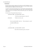
Manual Number: 00650-146-1
Page 14
PCI-COM485/8 Manual
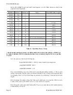
On the PCI-COM485/8 card, the UART clock frequency is 1.8432 MHz. Below is a table for the
popular divisor frequencies:
e
t
a
R
d
u
a
B
1
x
r
o
s
i
v
i
D
4
x
r
o
s
i
v
i
D
:
s
e
t
o
N
*
h
t
g
n
e
L
e
l
b
a
C
.
f
f
i
D
x
a
M
0
0
8
0
6
4
A
/
N
1
0
0
4
0
3
2
A
/
N
2
0
0
6
3
5
1
A
/
N
3
0
0
2
5
1
1
1
4
t
e
e
f
5
7
3
0
0
6
7
5
2
8
t
f
0
6
6
0
0
4
8
3
3
2
1
t
f
0
2
9
0
0
8
8
2
4
6
1
t
f
5
6
1
1
0
0
2
9
1
6
4
2
t
f
0
2
6
1
0
0
4
4
1
8
2
3
t
f
0
5
0
2
0
0
6
9
2
1
8
4
d
e
e
p
s
l
a
i
r
t
s
u
d
n
i
n
o
m
m
o
c
t
s
o
M
t
f
0
0
0
4
0
0
8
4
4
2
6
9
t
f
0
0
0
4
0
0
4
2
8
4
2
9
1
t
f
0
0
0
4
0
0
2
1
6
9
4
8
3
t
f
0
0
0
4
Table 5-1: Baud Rate Divisor Values
* Recommended maximum distances for differentially driven data cables (RS422 or RS-485) are
for typical conditions. RS-232 communication lines have a maximum length of 50 feet, regardless
of speed.
In C, the code to set the chip to 9600 baud is:
Outportb(BA3, 0X80);// enters baud-divisor setup mode
outportb(BASEADDR, 0x0C);
outportb(BA1,0);
The second initializing step is to set the Line Control Register at Base A3. This register
defines word length, stop bits, parity, and the DLAB. Bits 0 and 1 control word length and allow
word lengths from 5 to 8 bits. Bit settings are extracted by subtracting 5 from the desired word
length.
Bit 2 determines the number of stop bits. There can be either one or two stop bits. If Bit 2 is set to
0, there will be one stop bit. If Bit 2 is set to 1, there will be two stop bits.
Bits 3 through 6 control parity and break enable. They are not commonly used for communications
and should be set to zeroes.


