12. Serial EEPROM > System Diagram
102
PEB383 User Manual
July 25, 2011
Integrated Device Technology, Inc.
Confidential - NDA Required
12.2
System Diagram
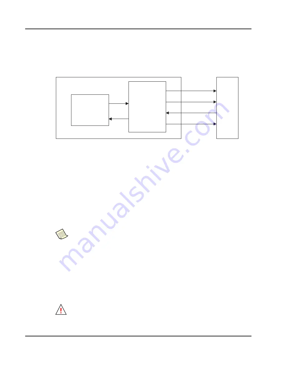
shows the EEPROM Controller interfacing an external EEPROM to the PEB383
configuration space.
Figure 30: EEPROM Interface
The PEB383 internal clock block generates an EEPROM clock of 7.8 MHz to supply to the external
EEPROM. This clock is derived from the PCIe clock of frequency 125 MHz.
The first two locations in the EEPROM – byte address 0x0000 and 0x0001 – contain the identification
code. The next two locations contain the byte count, which indicates the number of bytes to be read
from the EEPROM locations. After this, the next two locations of the EEPROM contain the CSR
address, and the byte enables to indicate the valid byte locations to be loaded from the EEPROM. The
next four locations after this contain the 4 bytes of data to be loaded into configuration space.
Thereafter, the data structure is maintained in the EEPROM, per register, as 2 bytes of address and byte
enables followed by 4 bytes of data. Therefore, the value in the third and fourth locations of the
EEPROM, which is the byte count, should always be a multiple of 6 since 6 bytes of information
(which includes address, byte enables, and data) is required to program one CSR register.
describes the data structure to be maintained by the external EEPROM.
After the reset is de-asserted, the EEPROM Controller initiates a read of the first two locations of the
external EEPROM to get the identification code. The identification code must be 0x28AB. Initially, it
initiates a read transaction with 9-bit address, and reads the identification code. If the identification
code results in a wrong value – that is, other than above value – then it initiates another read transaction
with a 16-bit address to read the identification code. If the value read is other than the identification
code, then it determines that an EEPROM is not present. It then sets this information in ADD_WIDTH
of the
, and aborts the programming of the configuration space by
signaling the completion of the loading.
If the byte count value is programmed to 0 or greater and is a non-multiple of 6, then the
EEPROM Controller rounds up this value to the next nearest value (which is a multiple of 6).
The EEPROM Controller then proceeds to program the CSR as per this new byte count value.
If a blank EEPROM is used, the ADD_WIDTH bits in the
be written with the correct bit pattern for the type of EEPROM
before
accessing the
EEPROM.
Configuration
Space Register
EEPROM
Controller
EEPROM
Device
PEB38x
SR_CLK
SR_CSn
SR_DOUT
SR_DIN


