7. Interrupt Handling
152
PowerSpan II User Manual
80A1010_MA001_09
Integrated Device Technology
www.idt.com
7.3.3
Interrupt Mapping
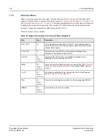
The following registers contain mapping bits for PowerSpan II interrupt sources:
•
IMR_MBOX (mailbox sources)
•
IMR_DB (doorbell sources)
•
IMR_DMA (DMA channel sources)
•
IMR_HW (external pin sources)
•
IMR_P1 (PCI-1 sources)
•
IMR_P2 (PCI-2 sources)
•
IMR_PB (Processor Bus sources)
•
IMR2_PB (Processor Bus sources)
•
IMR_MISC (I
2
O sources)
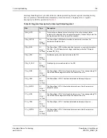
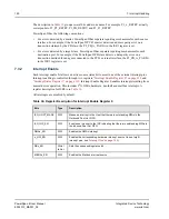
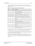
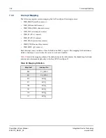
Each interrupt source contains a three bit field in an IMR_x register. This mapping field determines
which external pin to assert when the source is active and enabled.
details the mapping scheme. The shaded area in the table denotes the shaded map field and
interrupt pin information apply only to the Dual PCI PowerSpan II
Table 38: Mapping Definition
Map Field
Interrupt Pin
000
P1_INTA
#
001
P2_INTA
#
010
INT[0]_
011
INT[1]_
100
INT[2]_
101
INT[3]_
110
INT[4]_
111
INT[5]_


